
Apparatus and method employing microwave heating of hydrocarbon fluid

a technology of hydrocarbon fluid and apparatus, which is applied in the direction of thermal non-catalytic cracking, instruments, disinfection, etc., can solve the problems of thermally driven fouling on the inside of the reactor tube wall, requiring expensive infrastructure to be viable, and limited to refinery locations, so as to improve the control of the targeted visbreaking reaction, reduce the variability of the residence time, and reduce the effect of thermal fouling

Inactive Publication Date: 2016-04-07
SCHLUMBERGER TECH CORP
View PDF8 Cites 1 Cited by
  • Summary
  • Abstract
  • Description
  • Claims
  • Application Information

AI Technical Summary

Benefits of technology

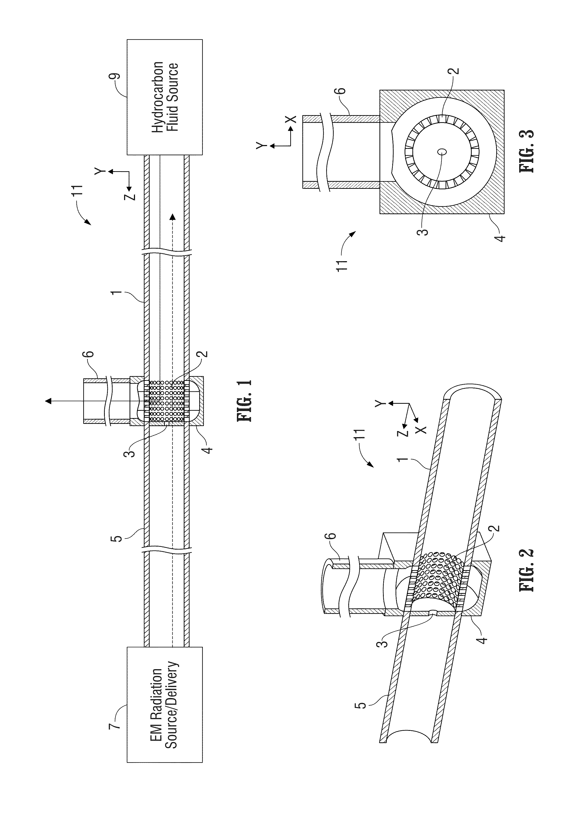
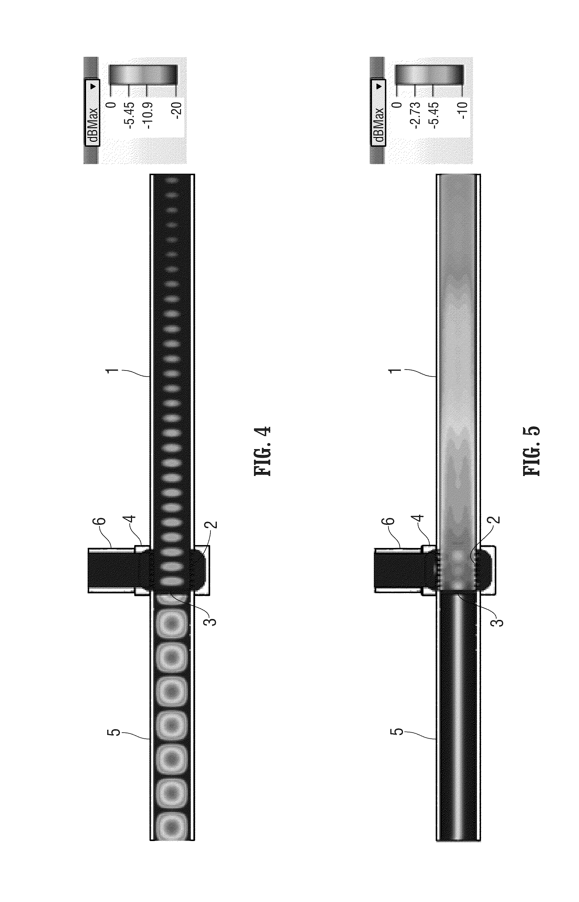
The patent describes a device that can transmit electromagnetic radiation through a hydrocarbon fluid. The device has a traveling wave structure that can be a sealed vessel containing the fluid and has a coupler to connect the electromagnetic radiation source. The coupler is designed to match the output impedance of the source to maximize power transfer. The device also has an electromagnetic transparent wall to prevent the fluid from flowing into the transmission line and allow the radiation to pass through. The device is designed to minimize energy loss and maximize energy efficiency.

Problems solved by technology

While heavy oil is becoming a regular feedstock to most refineries, its inherent high viscosity presents a challenge in transporting the heavy oil from the wellsite to commercial upgrading and refining facilities.
Such methods require large and readily available volumes of diluents as well as infrastructure to blend, transport, and recover the diluents at the other end of the pipeline.
Moreover, the conventional upgrading process can handle large production volumes in the range of ten thousand to hundreds of thousands of barrels / day and can require expensive infrastructure to be viable and is therefore limited to refinery locations.
While effective and relatively efficient, this mechanism introduces the risk of thermally-driven fouling on the inside of the reactor tube walls.

Method used


Image

  • Apparatus and method employing microwave heating of hydrocarbon fluid
  • Apparatus and method employing microwave heating of hydrocarbon fluid
  • Apparatus and method employing microwave heating of hydrocarbon fluid

Examples


Embodiment Construction

[0036]The particulars shown herein are by way of example and for purposes of illustrative discussion of the embodiments of the present application only and are presented in the cause of providing what is believed to be the most useful and readily understood description of the principles and conceptual aspects of the present application. In this regard, no attempt is made to show structural details in more detail than is necessary for the fundamental understanding of the present application, the description taken with the drawings making apparent to those skilled in the art how the several forms of the present application may be embodied in practice.

[0037]In the present application, the term electromagnetic (EM) radiation or energy or microwave radiation or energy or radio frequency (RF) radiation or energy refer to electromagnetic waves within the microwave radio-frequency band.

[0038]The term “traveling wave electromagnetic radiation” or “traveling wave EM radiation” is EM radiation...


PUM


Abstract

Apparatus for heating of hydrocarbon fluid where a traveling waveguide structure is configured to confine traveling wave electromagnetic radiation within its interior chamber and to contain hydrocarbon fluid that is subject to heating by such traveling wave electromagnetic radiation. The apparatus can be configured to heat hydrocarbon fluid to a reaction temperature suitable for visbreaking of the hydrocarbon fluid. The reaction temperature can be in the range of 350° C. to 500° C., which is suitable for visbreaking of heavy oil.

Description

BACKGROUND[0001]1. Field[0002]The present application relates generally to thermal processing of materials. More particularly, the present application relates to the use of electromagnetic radiation (such as microwave radiation) to promote a chemical process or reaction, such as visbreaking of a hydrocarbon fluid where the molecular bonds in hydrocarbon molecules are broken so that smaller or lighter hydrocarbons are created in order to irreversibly reduce the viscosity of the hydrocarbon fluid.[0003]2. Description of Related Art[0004]While heavy oil is becoming a regular feedstock to most refineries, its inherent high viscosity presents a challenge in transporting the heavy oil from the wellsite to commercial upgrading and refining facilities. A number of options have been or are currently used, including tanker shipments by rail, tanker truck, or barge, diluting of the heavy oil for pipeline transportation, and viscosity reduction by visbreaking for pipeline transportation.[0005]T...

Claims


Application Information

Patent Timeline
IPC IPC(8): C10G9/00B01J19/12
CPCC10G9/007B01J19/129B01J2219/1293B01J2219/0871B01J2219/1281B01J19/126C10G32/02
Inventor TAM, WAI-MINGTAYLOR, SHAWN DAVIDCLARK, BRIAN OLIVER
Owner SCHLUMBERGER TECH CORP
Learn More