
Temperature compensated beam resonator

a beam resonator and temperature compensation technology, applied in the field of microelectromechanical resonators, can solve the problems of high temperature drift of resonance frequency, significantly worse temperature performance of silicon resonators, and documenting, but not teaching how to achieve a broader stable temperature range of operation. , to achieve the effect of improving the quality factor of the resonator and avoiding parasitic resonance in the resonator

Active Publication Date: 2016-04-07
TEKNOLOGIAN TUTKIMUSKESKUS VTT
View PDF23 Cites 16 Cited by
  • Summary
  • Abstract
  • Description
  • Claims
  • Application Information

AI Technical Summary

Benefits of technology

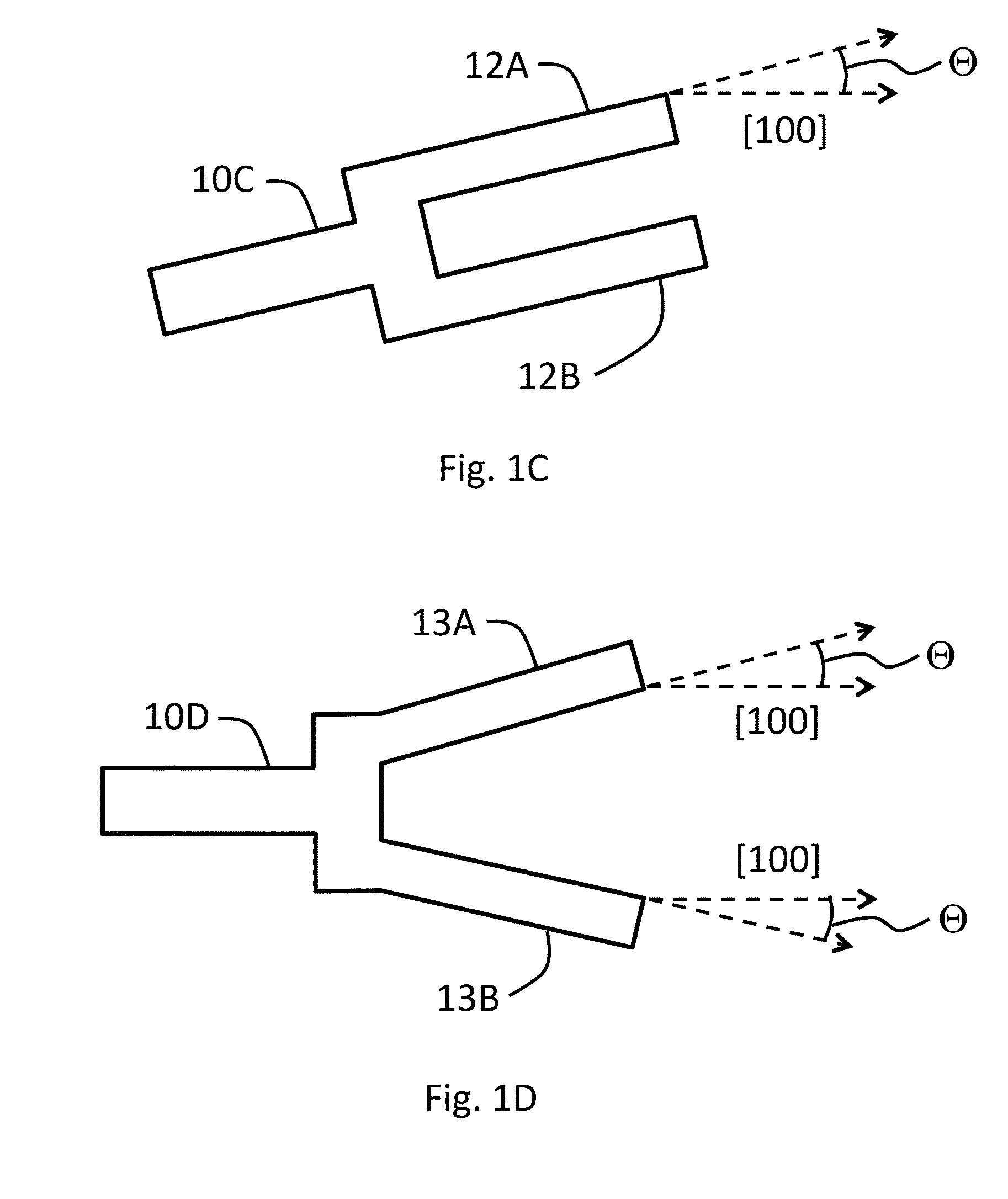
The invention provides a resonator with zero or close to zero second and optionally first order TCFs (thermal crosstalk), which ensures high frequency stability at varying temperatures. This is achieved using n-type doping concentration in one of the disclosed resonance modes. Compared to superlattice structures, the resonator is manufacturable as a monolithic one-layer element with simpler manufacturing process and requires smaller dopant concentrations. The resonator can also be designed with at least two beams having non-parallel orientation to avoid parasitic resonances and improve the quality factor of the resonator.

Problems solved by technology

However, a problem associated with silicon based resonators is that they have a high temperature drift of the resonance frequency.
The temperature performance of silicon resonators is considerably worse at the present.
The document, however, does not teach how to achieve a broader stable temperature range of operation, i.e., how to minimize the 2nd order TCF.
At the present, there are only few practically feasible low-TCF silicon resonator designs available, some of which are disclosed in WO 2012 / 110708 and U.S. Pat. No. 8,558,643.

Method used


Image

  • Temperature compensated beam resonator
  • Temperature compensated beam resonator
  • Temperature compensated beam resonator

Examples


Embodiment Construction

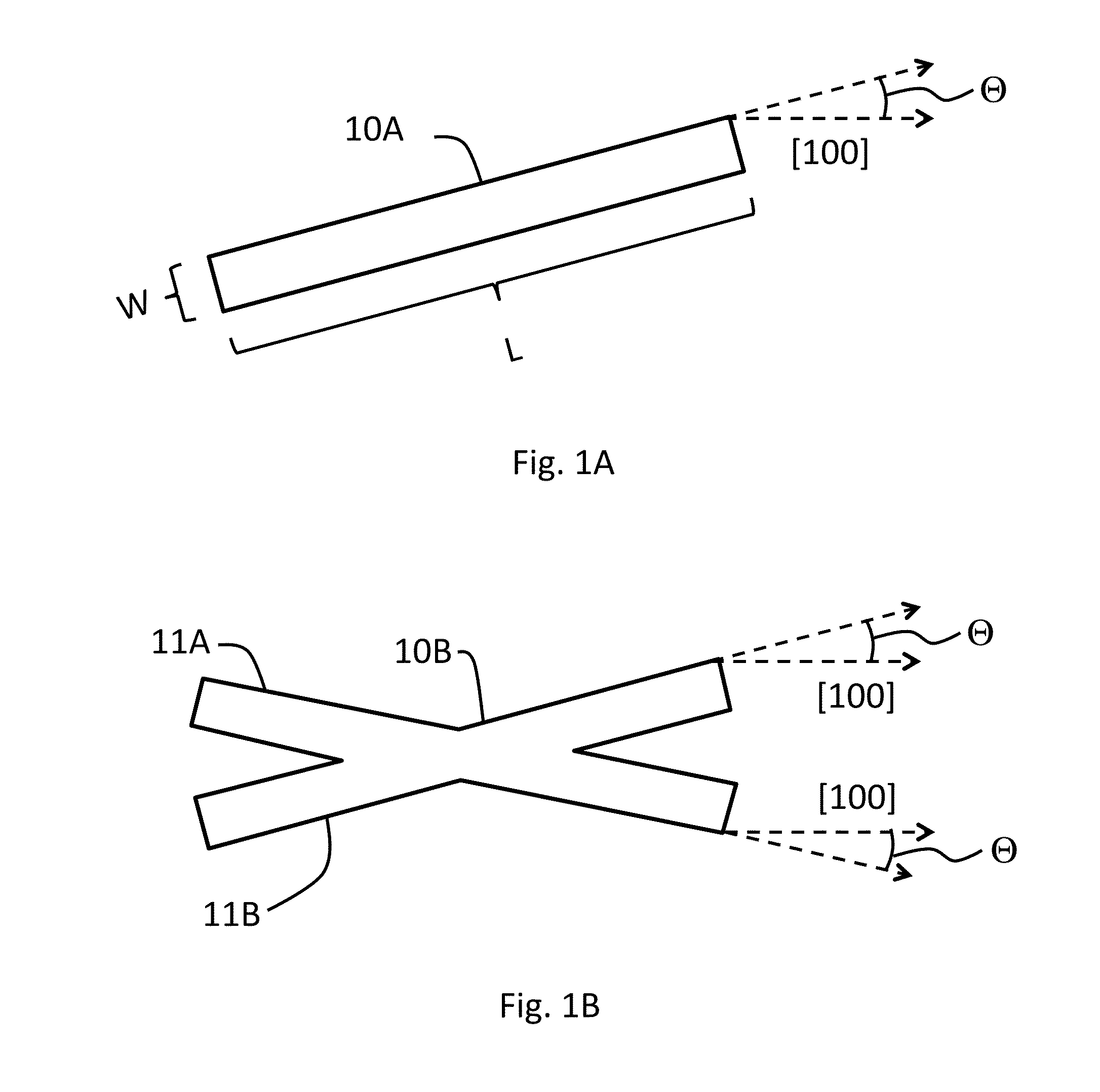
[0064]FIG. 1A shows a resonator consisting of a single beam 10A manufactured on a (100) wafer and having a length L and width W. The beam 10A is tilted with respect to the [100] crystal direction by an angle Θ. The tilted beam 10A can be anchored to the surrounding support structure (not shown) from an anchoring point at one longitudinal end thereof or in the middle of one or both longitudinal sides, depending on the intended resonance mode to be excited. Preferably anchoring takes place at one or more nodal or quasinodal points of the resonance mode at the perimeter of the beam 10A.

[0065]A drawback in the resonator of FIG. 1A is that it is not symmetric with respect to the [100] direction, whereby parasitic resonance modes may arise in the beam along with the main resonance mode. These parasitic modes may decrease the quality factor of the resonator, and may even affect the TCF characteristics of the main resonance mode.

[0066]The resonator of FIG. 1B avoids the drawback. It compris...


PUM


Abstract

The invention provides a microelectromechanical resonator device comprising a support structure and a resonator manufactured on a (100) or (110) semiconductor wafer, wherein the resonator is suspended to the support structure and comprises at least one beam being doped to a doping concentration of 1.1*1020 cm−3 or more with an n-type doping agent and is being capable of resonating in a length-extensional, flexural resonance or torsional mode upon suitable actuation. In particular, the doping concentration and angle of the beam are chosen so as to simultaneously produce zero or close to zero second order TCF, and even more preferably zero or close to zero first and second order TCFs, for the resonator in said resonance mode, thus providing a temperature stable resonator.

Description

FIELD OF THE INVENTION[0001]The invention relates to microelectromechanical resonators. In particular, the invention relates to adjusting temperature coefficient of frequency (TCF) of beam-containing resonators.BACKGROUND OF THE INVENTION[0002]Widely used quartz crystal based resonators can potentially be replaced by micromechanical, typically silicon-based, resonators in many applications. Silicon resonators can be made smaller than quartz resonators and there are a plurality standard manufacturing methods for silicon resonators. However, a problem associated with silicon based resonators is that they have a high temperature drift of the resonance frequency. The drift is mainly due to the temperature dependence of the Young modulus of silicon, which causes a temperature coefficient of frequency (TCF) approx. −30 ppm / C. This causes the resonance frequency to fluctuate due to changes in ambient temperature.[0003]As concerns the TCF, both the linear, i.e. 1st order, and 2nd order beha...

Claims


Application Information

Patent Timeline
Patent Type & Authority Applications(United States)
IPC IPC(8): H03H9/02H03H9/24
CPCH03H9/2405H03H9/02448H03H3/0076H03H9/2447H03H2009/241
Inventor JAAKKOLA, ANTTIPEKKO, PANUPRUNNILA, MIKAPENSALA, TUOMAS
Owner TEKNOLOGIAN TUTKIMUSKESKUS VTT
Learn More