Coating device and coating method

a coating device and coating technology, applied in the field of coating devices, can solve the problems of reducing the fire resistance of the honeycomb support element, and reducing the fire resistance of the composite honeycomb support element,

Active Publication Date: 2016-04-14
ISELI FREDY
View PDF0 Cites 1 Cited by
  • Summary
  • Abstract
  • Description
  • Claims
  • Application Information

AI Technical Summary

Benefits of technology

[0029]Of particular advantage is a form of embodiment of the coating device in which the placement of the composite pulp honeycomb support elements that are to be coated onto the means of conveyance takes place automatically, in particular from a stack. For this purpose a lifting table is preferably assigned to a stack of composite pulp honeycomb support elements, from which the composite pulp honeycomb support elements are placed onto the means of conveyance, in particular they are slid into place. Additionally or alternatively,...

Problems solved by technology

While the synthetic resin systems coming into use possibly increase the water resistance, they do not increase the fire resistance of the composite honeycomb support element.
Moreover, large- scale use of the method of known art turns out to be difficult, because only a batch process can be undertaken.
Also, with the method of known art the passages of the composite honeycomb support element cannot be coated with aqueous impregnation agents, since the paper honeycombs suck up the water and thereby lose strength; the honeycomb structure becomes soft and thereby disintegrates.
The coating device of known art does not operate continuously, but rather in batch mode, which is disadvantageous with regard to the coating rate.
Moreover, t...

Method used


Image

  • Coating device and coating method
  • Coating device and coating method

Examples


Embodiment Construction

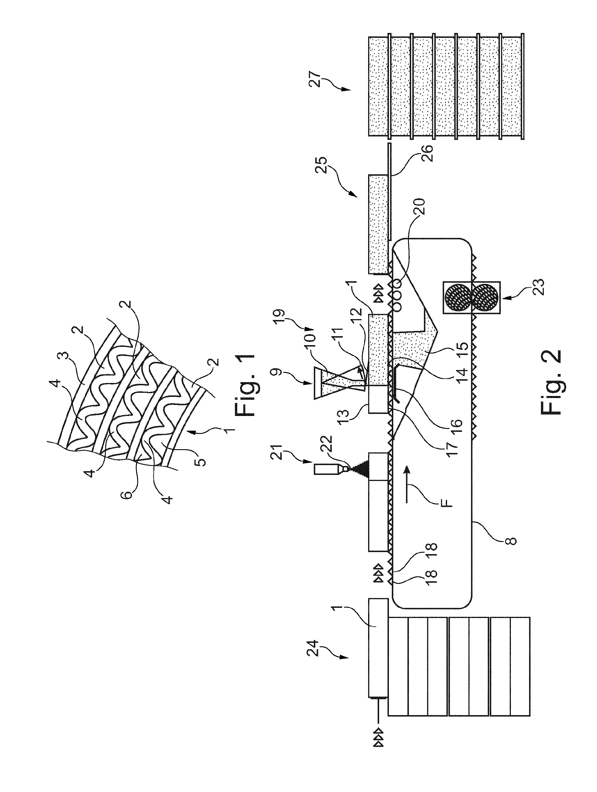
[0035]FIG. 1 shows a plan view onto a face of a composite pulp honeycomb support element 1 (here in the exemplary form of a corrugated board honeycomb body). The detail shown consists of three plies 2 (layers) glued together, wherein each ply 2 is formed from a flat carrier paper 3, which is glued together with a corrugated paper 4 to form (first) axial passages 5. The passages 5 are thus peripherally bounded by the corrugated paper 4 and the carrier paper 3. Furthermore each ply 2 comprises (second) passages 6, which in the example of embodiment shown are bounded by the above-cited corrugated paper 4 and a further carrier paper, namely the carrier paper of the adjacent (parallel) ply. In an alternative variant of embodiment, not illustrated, each ply 2 can also comprise two carrier papers, which accommodate the corrugated paper 4 between them in the form of a sandwich. In this case the (second) passages 6 are bounded by the paper and a carrier paper 3 of the same ply.

[0036]As can b...


PUM

PropertyMeasurementUnit
Lengthaaaaaaaaaa
Electrical resistanceaaaaaaaaaa
Mechanical stabilityaaaaaaaaaa

Abstract

A coating device for coating composite cellulose honeycomb support parts (1), each having a multiplicity of channels (5, 6) extending in an axial direction, having an impregnation coating to increase fire- and/or water-resistance and/or mechanical stability. A conveyor (8) is provided for transporting the composite cellulose honeycomb support parts (1) in a conveying direction along a filling station (9), which is configured in such a manner that the filling station (9) can be used to pour impregnation agent (12) from above into the channels (5, 6) of the composite cellulose honeycomb support parts (1), and damming agents (16) are provided in the region of the filling station (9) and are configured in such a manner that the impregnation agent (12) is prevented or at least delayed from draining downwards out of the channels (5, 6) in such a manner that the impregnation agent (12) can build up in the channels (5, 6), in particular up to an upper side of the composite cellulose honeycomb support parts (1), and for an emptying station (19) to be arranged downstream of the filling station (9) in the conveying direction, at which emptying station excess impregnation agent (12) can drain out of the channels (5, 6) in the composite cellulose honeycomb support parts (1).

Description

BACKGROUND OF THE INVENTION[0001]The invention relates to a coating device for coating composite pulp (cellulose) honeycomb support elements, each having a multiplicity of passages extending in an axial direction, with an impregnation coating for the purpose of increasing the fire and / or water resistance and / or the mechanical stability. The invention furthermore relates to a coating method for the purpose of coating such pulp sheets.[0002]Composite honeycomb support elements are of known art, in particular when deployed as a honeycomb core material in composite sheets, wherein the honeycombs of the composite honeycomb support elements are formed from a multiplicity of passages extending in an axial direction, which as a rule are peripherally bounded by carrier papers, together with corrugated papers glued together with the carrier papers.[0003]A method for the manufacture of composite honeycomb support elements is, for example, described in DE 103 05 747 A1. Other composite honeycom...

Claims


Application Information

Patent Timeline
IPC IPC(8): D21H23/48B05C11/10B05C13/02B05C5/00
CPCD21H23/48B05C13/02B05C11/1039B05C5/005B29D99/0089B31D3/02B31D3/0292B32B3/12B29K2311/126B32B29/005B32B2250/26B32B2260/028B32B2260/046B32B2307/3065B32B2307/7265B05D7/22B05C7/04
Inventor ISELI, FREDY
Owner ISELI FREDY
Why Eureka
Try Eureka