Ultrasonic transmission and reception device

Active Publication Date: 2016-04-14
ROBERT BOSCH GMBH
View PDF1 Cites 0 Cited by
  • Summary
  • Abstract
  • Description
  • Claims
  • Application Information

AI Technical Summary

Benefits of technology

The present invention is related to an ultrasonic transmission and reception device. The device includes a transmission circuit, an ultrasonic transducer, a transformer, and a reception circuit. The device is characterized in that the reception input of the reception circuit is connected to the transformer via an additional winding tap of the transformer, which boosts the transformed transmission signal at the reception input of the reception circuit with a lower gain factor than the transmission signal which excites the ultrasonic transducer. This allows for independent control of the reception and transmission circuits without the need for additional components. The transformer has a primary coil with one or more windings, and the reception circuit is connected to the primary coil through all the windings. The ratio between the numbers of windings is selected in such a way that a transmission signal does not exceed the proof voltage of the reception circuit. The device also includes a connectable damping resistor to minimize damping of the ultrasonic transducer during the transmission phase and a short cycle between successive transmission and receiving phases. The damping resistor can be connected to the same winding segment as the transmission circuit, which reduces costs and space requirements.

Problems solved by technology

Since this reception circuit is suited for evaluating very low amplitude echo signals, its proof voltage is limited.
However, these protective measures for protecting the reception circuit entail additional costs in the manufacture of the ultrasound transmission and reception device due to expensive or additional components.
Thus, half of the power output in the reception path is channeled off unnecessarily.

Method used


Image

  • Ultrasonic transmission and reception device
  • Ultrasonic transmission and reception device
  • Ultrasonic transmission and reception device

Examples


Embodiment Construction

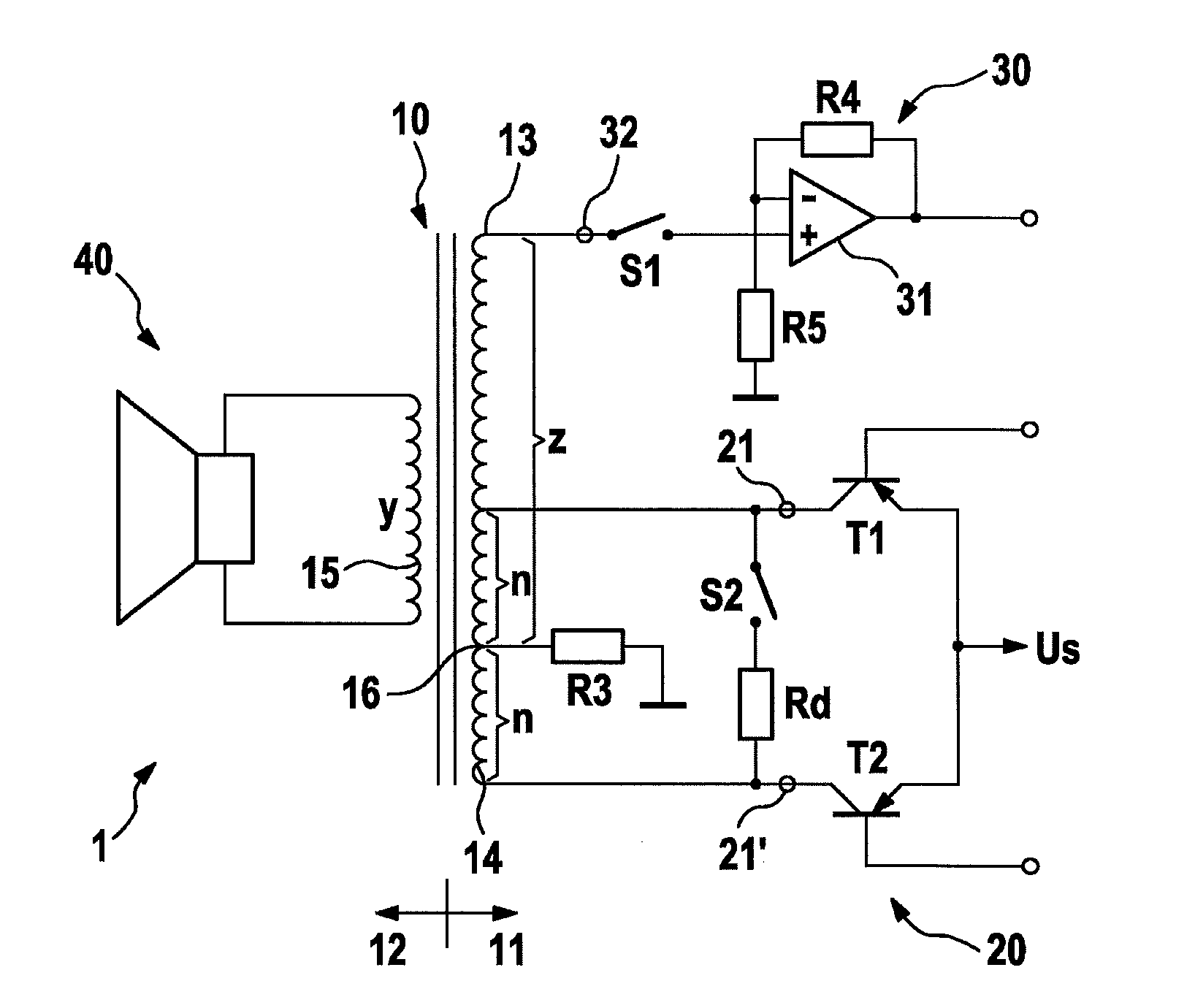
[0023]FIG. 1 shows a circuit diagram of an ultrasonic transmission and reception device 1 according to a first specific embodiment of the present invention. Transmission circuit 20 is used to generate a transmission signal at two signal outputs 21 and 21′. In this specific embodiment, transmission circuit 20 is supplied with a direct voltage Us, which is present between an input line and the ground potential of ultrasonic transmission and reception device 1. Direct voltage Us is present at the emitters of the two PNP transistors T1 and T2 of transmission circuit 20, and may be switched by these. To generate a transmission signal, the two transistors T1 and T2 are alternatingly switched. The switching of transistors T1 and T2 in this case occurs via two switching signals phase-shifted relative to one another, each of which is delivered to the base of transistors T1 and T2. The signal source for the switching signals is not shown in FIG. 1. If direct voltage Us is put through by one o...


PUM


Abstract

An ultrasonic transmission and reception device is described. This includes a transmission circuit for generating a transmission signal at its transmission outputs and, an ultrasonic transducer, which is suited for converting electrical signals into sound signals and sound signals into electrical signals, a transformer, the primary side of which is connected to the transmission outputs and of the transmission circuit and the secondary side of which is connected to the ultrasonic transducer, and a reception circuit for processing a received signal present at its reception input. The ultrasonic transmission and reception device is characterized in that the reception input of the reception circuit is connected to the transformer via an additional winding tap of the transformer, the additional winding tap being incorporated into the transformer in such a way that the transformed transmission signal at the reception input of the reception circuit is boosted in its voltage amplitude with a lower gain factor than the transformed transmission signal which excites the ultrasonic transducer.

Description

FIELD OF THE INVENTION[0001]The present invention relates to an ultrasonic transmission and reception device including a transformer.BACKGROUND INFORMATION[0002]Ultrasonic parking systems assist drivers with everyday parking maneuvers. A fully equipped ultrasonic parking system currently includes 12 ultrasonic sensors, 6 sensors each being situated in the front and the rear. In this system, objects at a distance of a few centimeters as well as of several meters may be detected. To achieve ranges of several meters and, at the same time, maintain the proximity measuring capability, an ultrasonic transmission and reception device must optimally utilize the available energy and at the same time hold the decay time to a minimum.[0003]In an ultrasonic transmission and reception device, a high-frequency alternating voltage signal is generated as a transmission signal by a transmission circuit. This alternating voltage signal is applied during a transmission phase to an ultrasonic transduce...

Claims


Application Information

Patent Timeline
IPC IPC(8): G01S7/526G01S15/93G01S15/931
CPCG01S15/931G01S7/526G01S7/523
Inventor RICHTER, KARL-HEINZSCHMID, DIRKBARTYLLA, DAVID
Owner ROBERT BOSCH GMBH
Why Eureka
Try Eureka