
Reducing error correction latency in a data storage system having lossy storage media

Inactive Publication Date: 2016-04-14
IBM CORP
View PDF16 Cites 4 Cited by
  • Summary
  • Abstract
  • Description
  • Claims
  • Application Information

AI Technical Summary

Benefits of technology

The patent describes a method for reducing read latency in a data storage system with lossy storage media. The method involves fetching target data from the lossy storage device into a buffer, transferring the data to an external controller, performing error location processing on the data, communicating the error information to error repair logic, and using the error repair logic to fix the errors in the data. The external controller then sends the repaired data to the destination. This method helps to improve the speed and efficiency of data storage and retrieval.

Problems solved by technology

Heretofore, there has not been a compelling reason to evaluate the limitations of the serialization of the suboperations comprising a read operation in data storage systems having lossy storage media, such as flash memory.
However, as flash array cell densities and the number of bits stored per flash memory cell continue to increase in subsequent generations of flash technology, the data stored in the memory cells to become more vulnerable to bit errors induced by read disturbs, high ambient temperatures, long storage durations and other factors.

Method used


Image

  • Reducing error correction latency in a data storage system having lossy storage media
  • Reducing error correction latency in a data storage system having lossy storage media
  • Reducing error correction latency in a data storage system having lossy storage media

Examples


Embodiment Construction

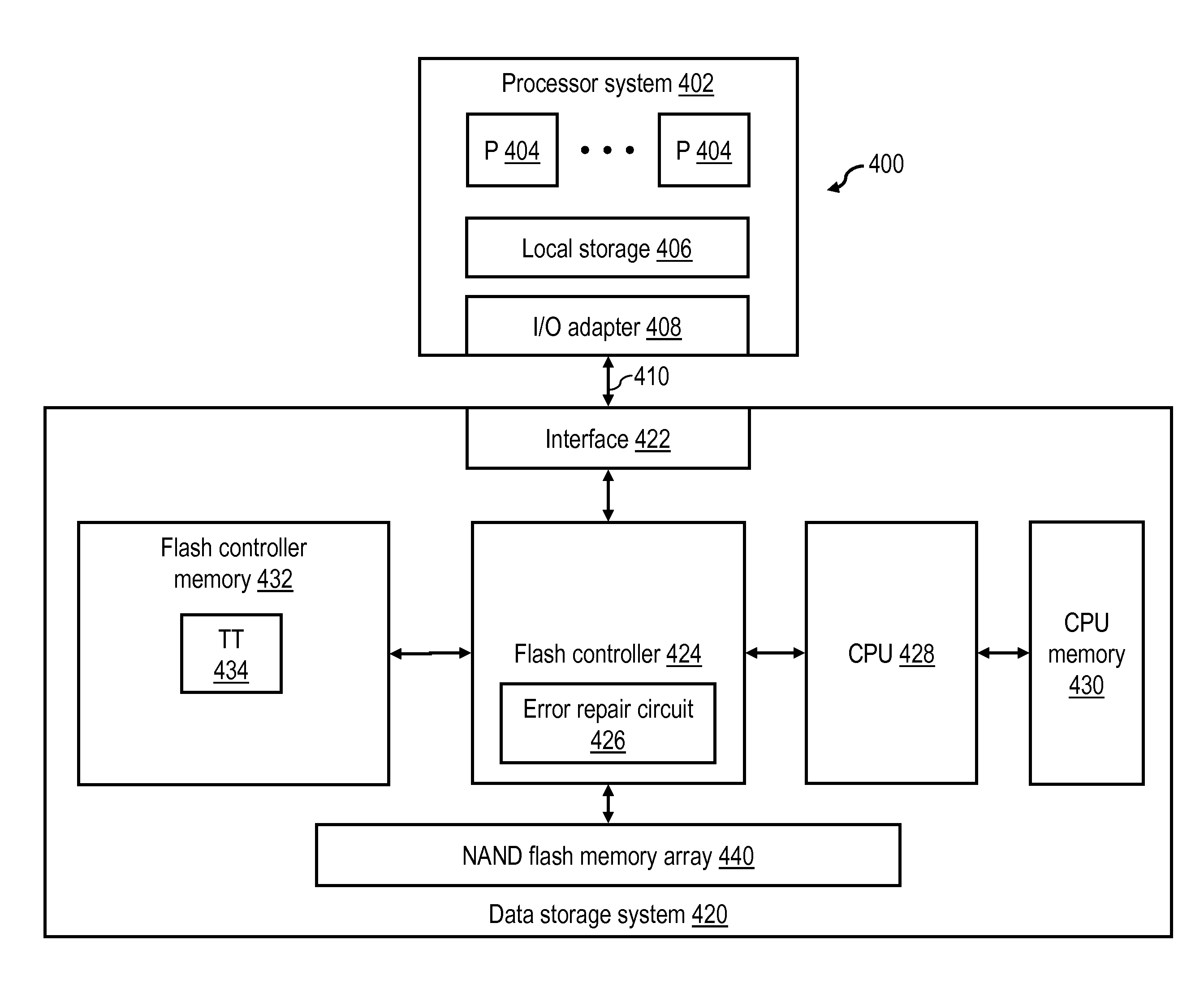
[0018]With reference again to the figures and with particular reference to FIG. 4, there is illustrated a high level block diagram of an exemplary data processing environment 400 including a data storage system having lossy storage media as described further herein. As shown, data processing environment 400 includes at least one processor system 402 having one or more processors 404 that process instructions and data. Processor system 402 may additionally include local storage 406 (e.g., dynamic random access memory (DRAM) or disks) that may store program code, operands and / or execution results of the processing performed by processor(s) 404. In various embodiments, processor system 402 can be, for example, a mobile computing device (such as a smartphone or tablet), a laptop or desktop personal computer system, a server computer system (such as one of the POWER series available from International Business Machines Corporation), or a mainframe computer system. Processor system 402 ca...


PUM


Abstract

In at least one embodiment, a read operation in a data storage system having lossy storage media includes fetching target data of the read operation from a lossy storage device into a buffer, transferring the target data from the buffer to an external controller external to the lossy storage device via a communication bus, performing error location processing on the target data during the transferring of the target data, communicating error location information regarding at least one error location to error repair logic via the communication bus, the error repair logic repairing the at least one error in the target data using the error location information, and the external controller causing the target data as repaired to be transmitted toward a destination. By deserializing the suboperations comprising the read operation, read latency can be reduced.

Description

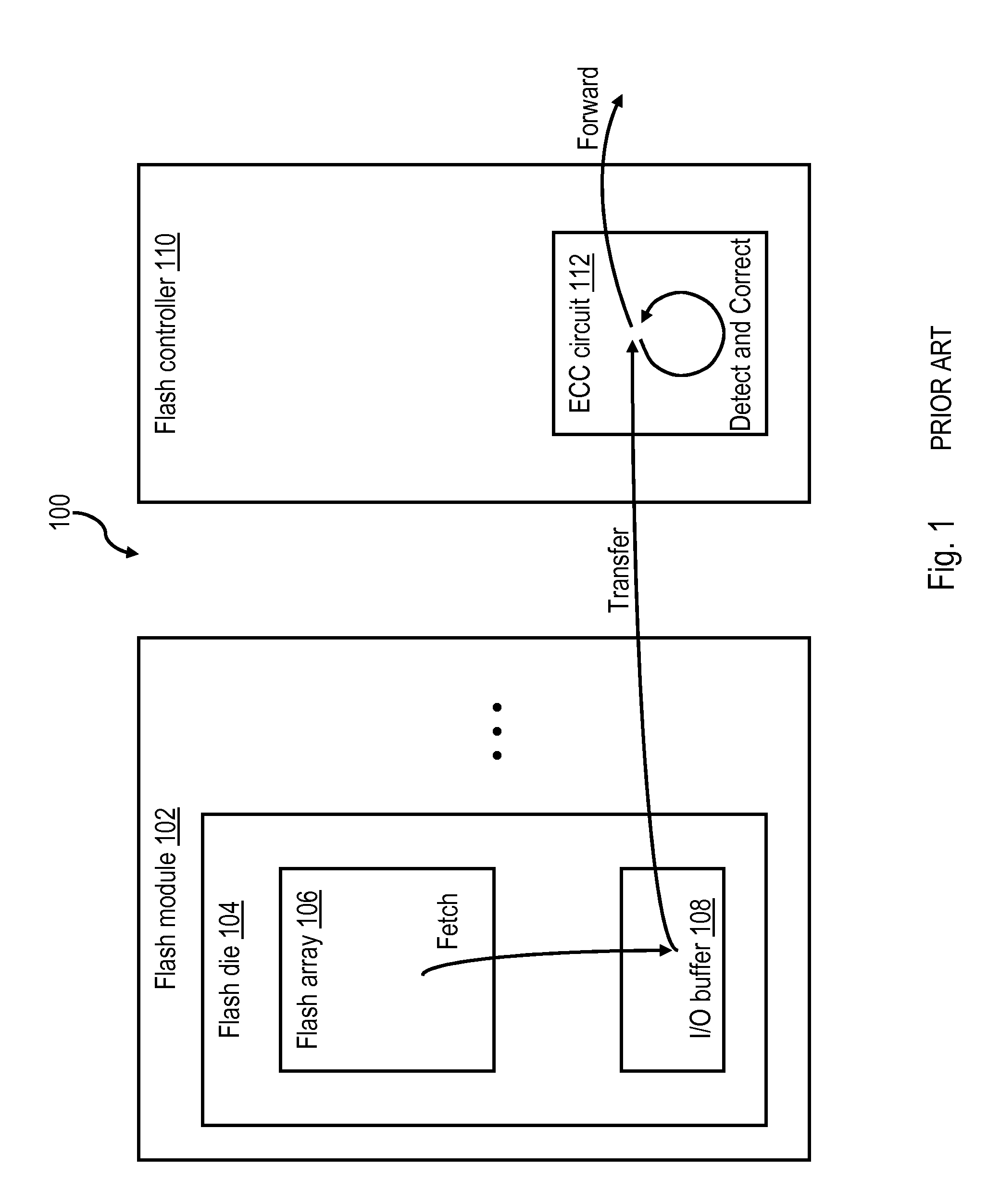
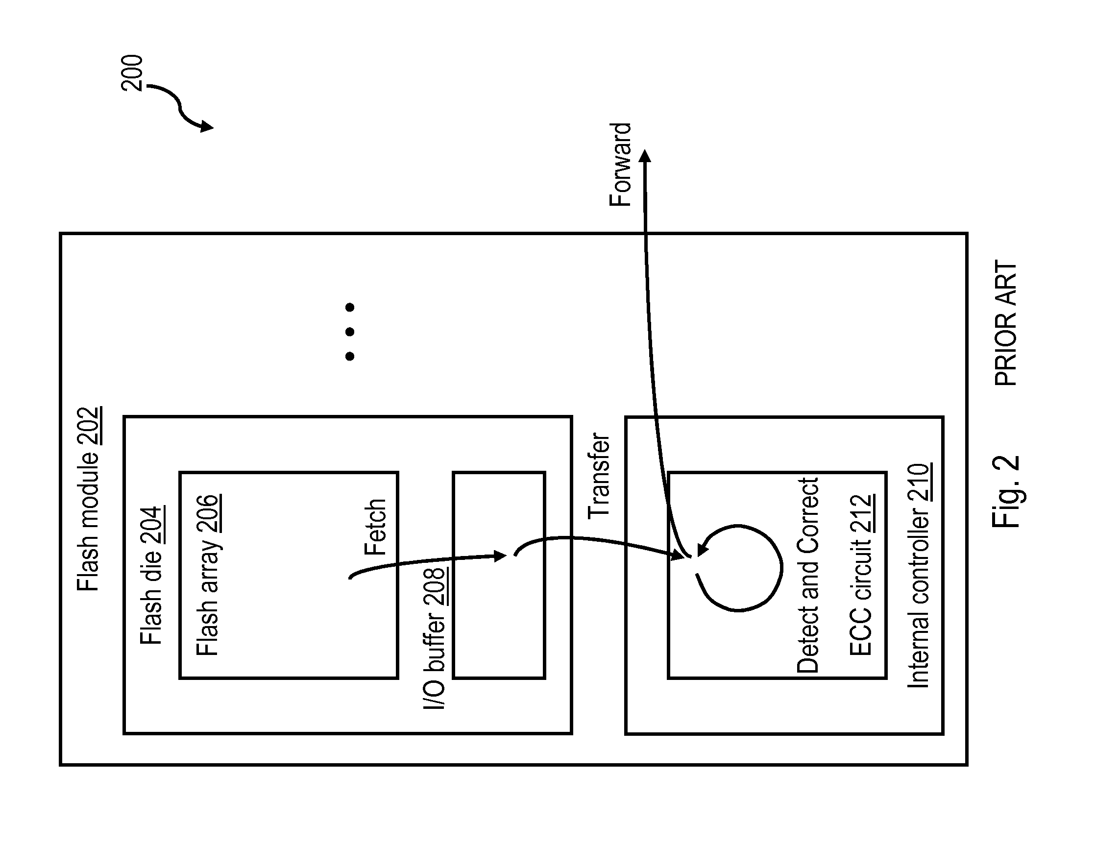
BACKGROUND OF THE INVENTION[0001]This disclosure relates to data processing and storage, and more specifically, to reducing error correction latency in a data storage system having lossy storage media, such as flash memory.[0002]Flash memory is a non-volatile memory technology that stores one or more bits of data per memory cell as a charge on the floating gate of a transistor. FIG. 1 illustrates a conventional flash memory system 100, which includes one or more flash modules 102 each including multiple flash die 104 (only one of which is illustrated). Each flash die 104 in turn includes a flash array 106, which includes a plurality of memory cells for storing one or more bits of data, and an input / output (I / O) buffer 108, which temporarily buffers data read from and written into flash array 106. The operation of the flash module(s) 102 and read and write accesses to flash array 106 are controlled by an external flash controller 110 typically coupled to flash module 102 by a communi...

Claims


Application Information

Patent Timeline
IPC IPC(8): G06F11/10G11C29/52
CPCG11C29/52G06F11/1068G06F11/1048G11C16/3418G11C2029/0411
Inventor CAMP, CHARLES J.ELEFTHERIOU, EVANGELOS S.POZIDIS, CHARALAMPOSTRESSLER, GARY A.WALLS, ANDREW D.
Owner IBM CORP
Learn More