Blade system, and corresponding method of manufacturing a blade system

a blade system and blade technology, applied in the field of blade systems, can solve the problems of high cycle fatigue, affecting the maintenance performance of blades, and affecting the maintenance performance of blades, and achieve the effect of improving the maintenance performan

Inactive Publication Date: 2016-04-21
SIEMENS AG
View PDF4 Cites 4 Cited by
  • Summary
  • Abstract
  • Description
  • Claims
  • Application Information

AI Technical Summary

Benefits of technology

[0015]It may be an objective of the present invention to provide a blad

Problems solved by technology

Turbine blades are subjected to dynamic loading of a blade airfoil leading to harmful vibrations and high cycle fatigue.
Also, as the blades are assembled, a twist may be induced in the blade airfoil which requires a high level of force for the blade assembly.
For these reasons, a single blade cannot be wit

Method used


Image

  • Blade system, and corresponding method of manufacturing a blade system
  • Blade system, and corresponding method of manufacturing a blade system
  • Blade system, and corresponding method of manufacturing a blade system

Examples


Embodiment Construction

[0051]The illustrations in the drawings are schematic. It is noted that in different figures similar or identical elements are provided with the same reference signs.

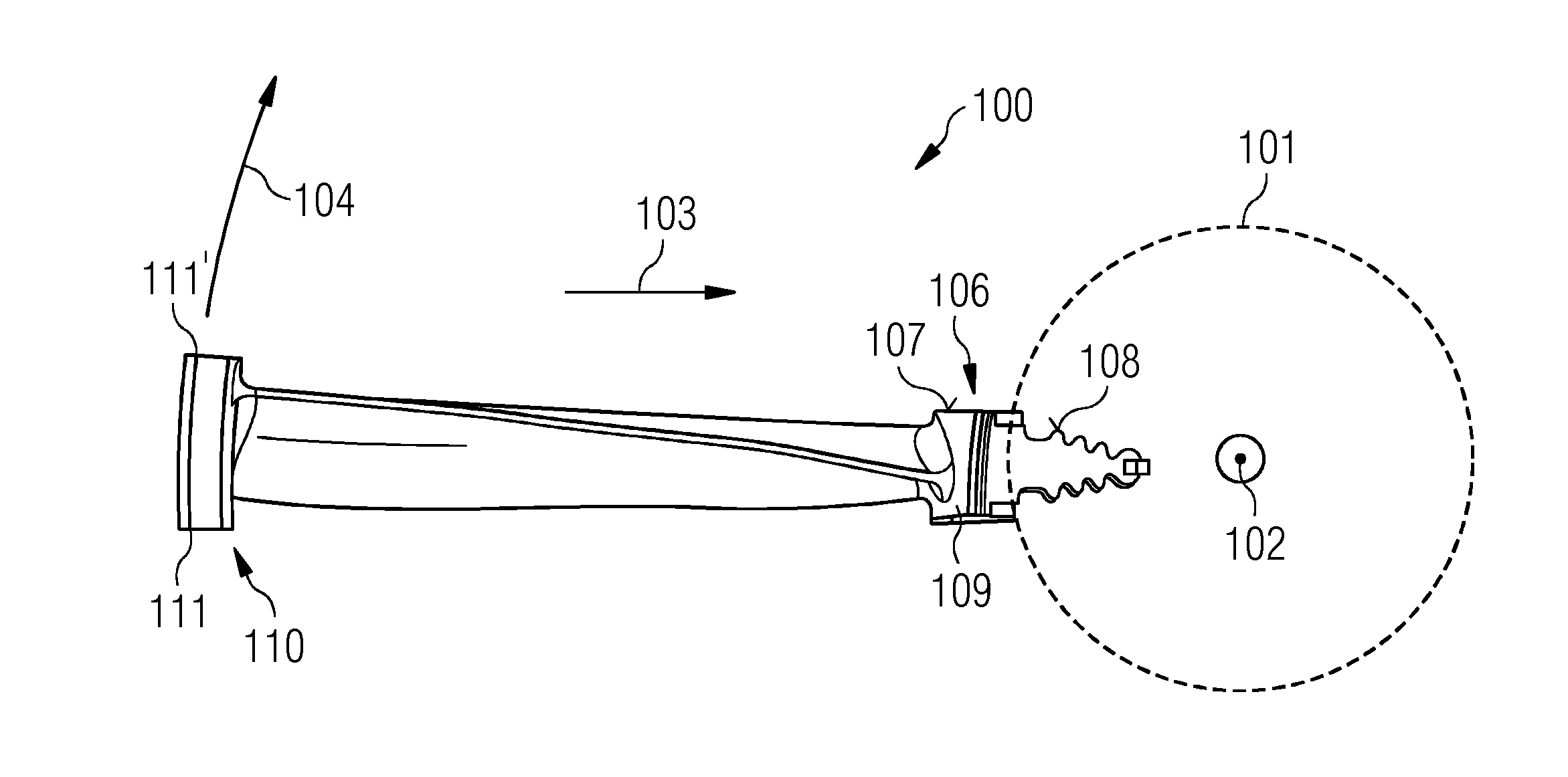
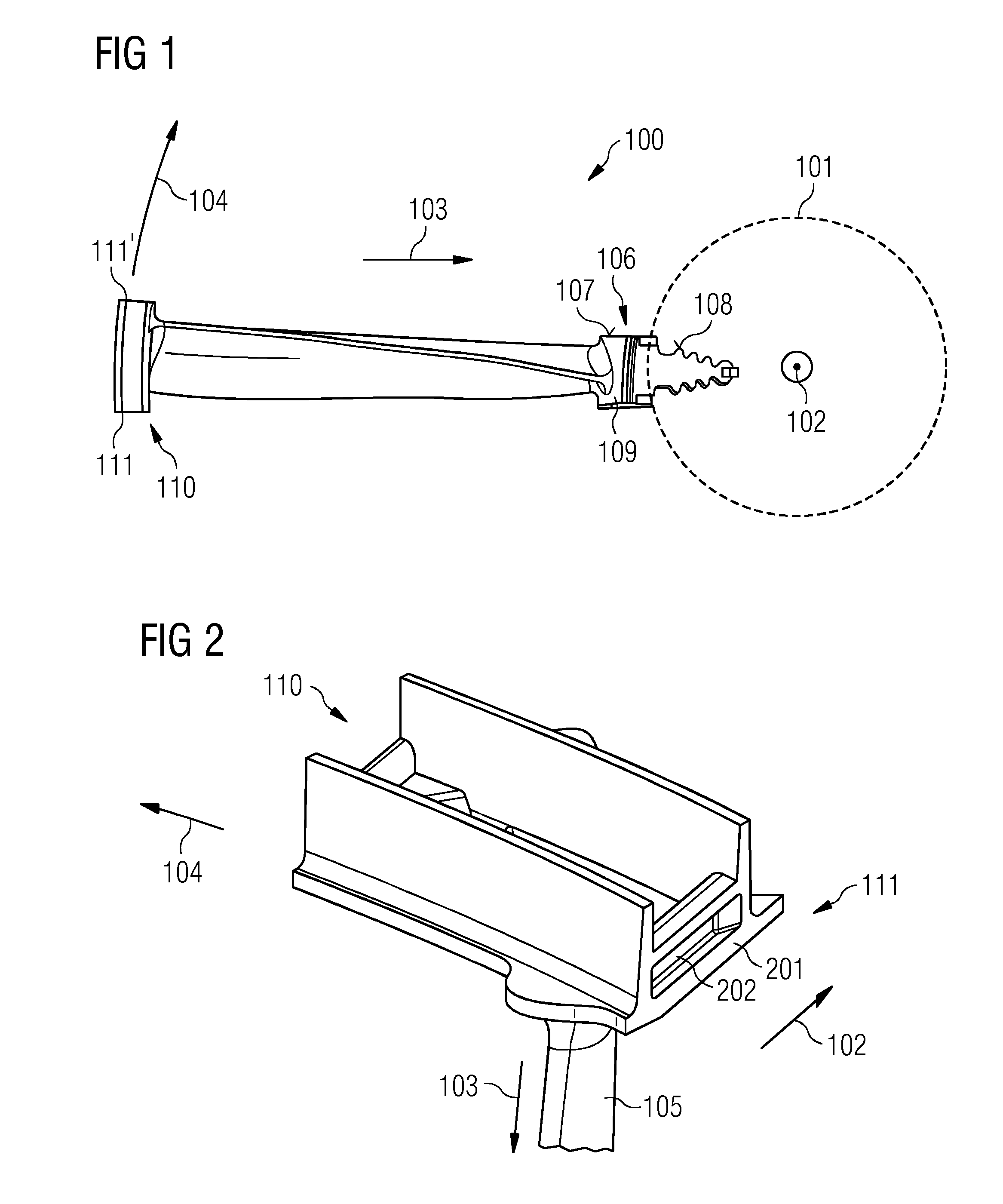
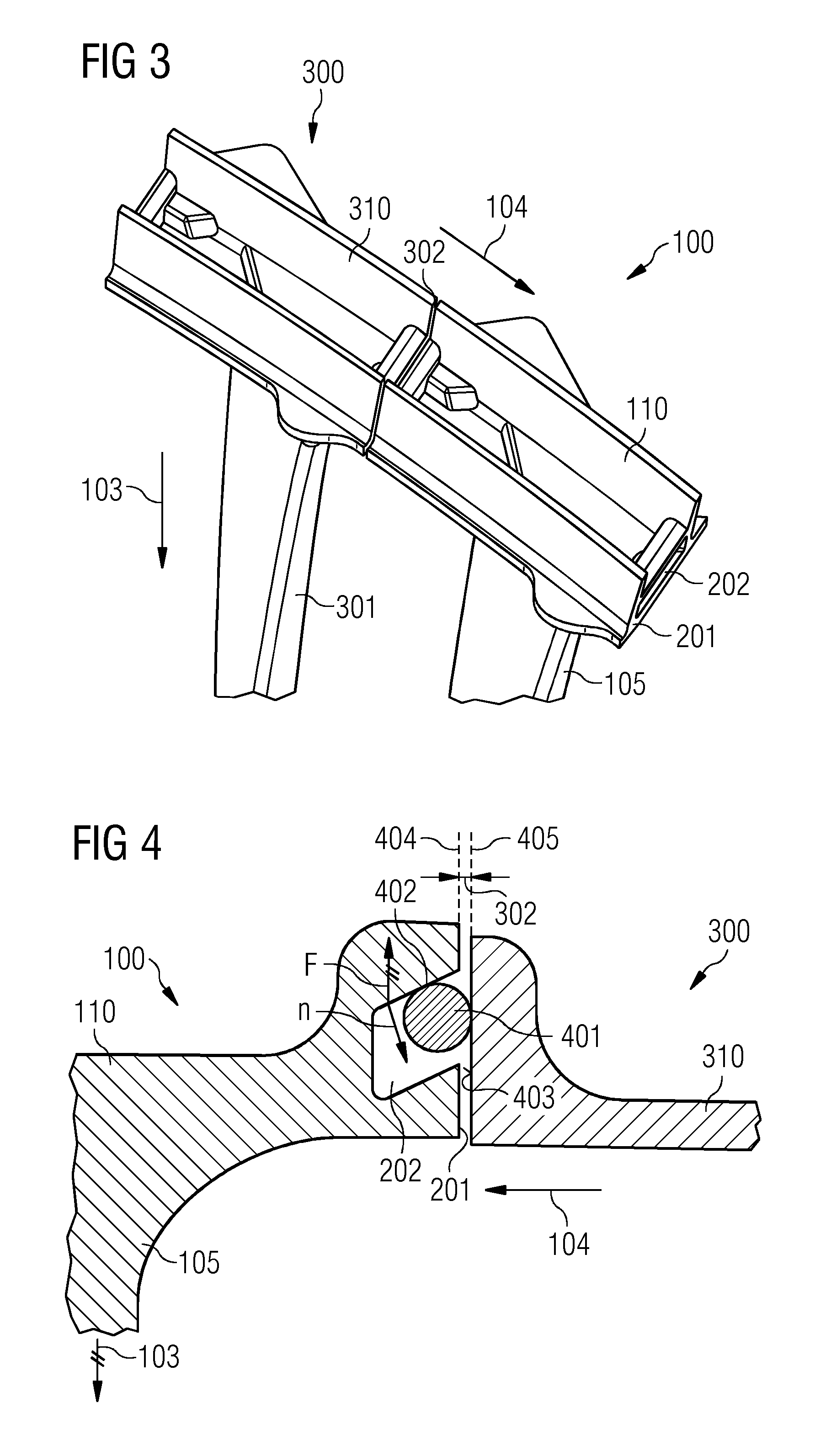
[0052]FIG. 1 shows a blade device 100 for a gas turbine. For a better understanding, the extensions and orientations of the features of the blade device 100 are described with respect to predefined directions of a rotor shaft 101 (indicated by dotted lines) of the gas turbine. The rotor shaft 101 comprises an axial direction 102 which is parallel to a rotary axis of the rotor shaft 101. Furthermore, a radial direction 103 is described which directs to the center axis (rotary shaft) of the rotor shaft 101. The circumferential direction 104 is perpendicular to the axial direction 102 and the radial direction 103. Along the circumferential direction 104, a plurality of blade devices 100 may be arranged one after another.

[0053]The blade device 100 comprises a shroud 110 and a blade root 106. An airfoil 105 extends along the...


PUM


Abstract

A blade system for a gas turbine has a blade device and a further blade device. The blade device has a shroud, an airfoil extending from the shroud along the radial direction, the shroud has at a circumferential end a wedge face having a recess extending with a component along the axial direction, and a damping wire arranged within the recess such that the damping wire is adapted for contacting the shroud and a further wedge face of a further shroud of a further blade device arranged adjacent to the shroud along the circumferential direction. The recess includes an inclining side surface which has a normal, non-parallel with the radial direction, the further wedge face has a plane surface onto which the damping wire is abuttable. A method of manufacturing a blade system includes arranging the further shroud adjacent to the shroud and arranging a damping wire within the recess.

Description

CROSS REFERENCE TO RELATED APPLICATIONS[0001]This application is the US National Stage of International Application No. PCT / EP2014 / 056802 filed Apr. 4, 2014, and claims the benefit thereof. The International Application claims the benefit of European Application No. EP13167446 filed May 13, 2013. All of the applications are incorporated by reference herein in their entirety.FIELD OF INVENTION[0002]The present invention relates to a blade device for a gas turbine and to a blade system for a gas turbine comprising the blade device. Furthermore, the present invention relates to a method of manufacturing the blade system for a gas turbine.ART BACKGROUND[0003]Turbine blades are subjected to dynamic loading of a blade airfoil leading to harmful vibrations and high cycle fatigue. This is particularly the case for so-called long slender blades which are more prone to their natural resonance interacting with the frequency of loading within the running speed range of the turbine. Traditionall...

Claims


Application Information

Patent Timeline
IPC IPC(8): F01D5/16F01D5/14
CPCF01D5/147F01D5/16F01D5/225F01D5/24F01D11/006Y02T50/60F01D5/3007
Inventor BATT, STEPHENMCKENNA, MIKE
Owner SIEMENS AG
Why Eureka
Try Eureka