Methods for determining receiver coupling efficiency, link margin, and link topology in active optical cables

a receiver coupling efficiency and active optical cable technology, applied in the field of active optical cables, can solve the problems of difficult or impossible measurement of receiver coupling efficiency, difficult or impossible measurement of how well the optical fiber is aligned with the lens or how, and the problem of both full and half aocs

Active Publication Date: 2016-04-21
SAMTEC
View PDF4 Cites 8 Cited by
  • Summary
  • Abstract
  • Description
  • Claims
  • Application Information

AI Technical Summary

Benefits of technology

[0028]The above and other features, elements, characteristics, steps, and advantages of the present invention will become more apparent from the following detailed description of preferred embodiments of the present invention with reference to the attached drawings.

Problems solved by technology

Without a received signal strength indicator (RSSI) on a limiting TIA, the receiver coupling efficiency is difficult or impossible to measure.
It is difficult or impossible to measure how well the optical fiber is aligned with the lens or how well the lens is aligned with the photodetector.
This problem exists for both full and half AOCs.
It is difficult or impossible to measure how well the optical fiber is aligned with the lens or how well the lens is aligned with the laser for full AOCs.
Further, the receiver and transmitter coupling efficiency cannot be measured in a closed link of either a full AOC or a mated pair of half AOCs.
However, the receiver coupling efficiency cannot be determined because the power that actually reaches the photodetector cannot be determined.
The amount of light that is in the optical fiber at the receiver is also unknown, which makes it impossible to know the receiver coupling efficiency between the fiber and the photodetector that is inside the receiver.
However, there is no currently known method to determine how much light actually reaches the receiver, which is the value that is of most concern.
However, the bit-error-rate measurement is time consuming and can only be performed on half AOCs.
Bit-error-rate measurement cannot be performed on full AOCs because bit-error rate measurement requires that the output power of the transmitter be adjusted to known levels while maintaining RF performance.
While it is possible to change the drive current of the laser, which will adjust the transmitted power, it is difficult to change the drive current while transmitting a signal.
However, not all TIAs have an integrated RSSI function.
Because the current cannot be measured, it is not possible to determine how much light is being received by the photodetector.
In systems with numerous links, the topology of the links can be difficult to determine.

Method used


Image

  • Methods for determining receiver coupling efficiency, link margin, and link topology in active optical cables
  • Methods for determining receiver coupling efficiency, link margin, and link topology in active optical cables
  • Methods for determining receiver coupling efficiency, link margin, and link topology in active optical cables

Examples


Embodiment Construction

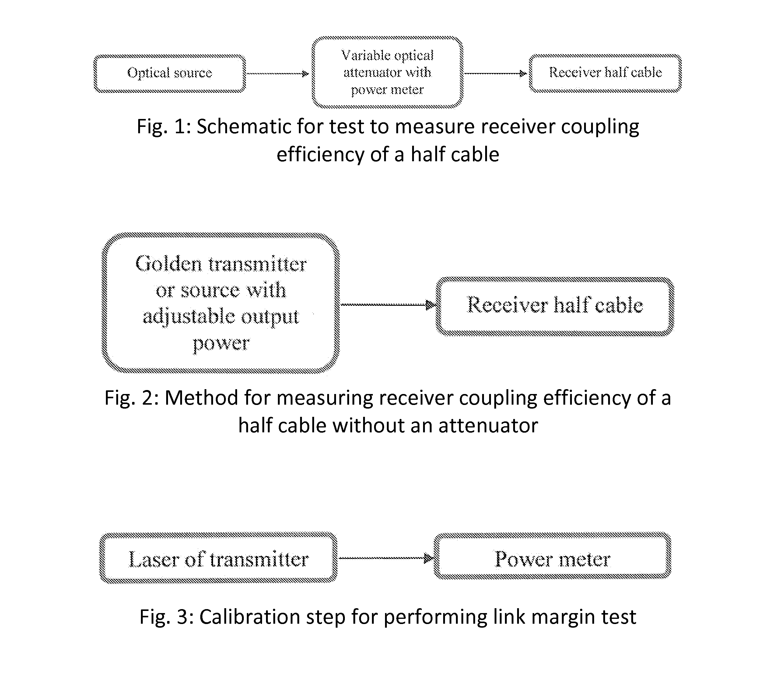
[0044]The preferred embodiments of the present invention provide methods for determining receiver coupling efficiency, link margin, and link topology in AOCs. The methods of the preferred embodiments are grouped into the following subsets:[0045]1) a test that can be used to measure the receiver coupling efficiency of half AOCs;[0046]2) a test that can be used to measure the link margin for closed links with full AOCs or mated pairs of half AOCs; and[0047]3) a test that can be used to determine which receiver is mated to a given transmitter to determine link topology.

Receiver Coupling Efficiency

[0048]The receiver coupling efficiency can be measured using a method according to a preferred embodiment of the present invention by injecting a known amount of optical power and by recording when the TIA goes into squelch.

[0049]Optical signals are typically transmitted as digital signals, i.e., as zeros and ones. Optical zero signals are transmitted at a reduced power level, e.g. 50% of the ...


PUM


Abstract

A method for determining receiver coupling efficiency includes varying optical power inputted into a half active optical cable to determine a maximum optical power at which the TIA squelches and determining a receiver coupling efficiency by calculating a ratio of a threshold optical power to the maximum optical power at which the TIA squelches. A method of determining link loss in a channel includes varying optical power of a light source to determine the maximum optical power at which the TIA squelches and determining the link loss in the channel by subtracting the maximum optical power from the threshold optical power. A method of determining link topology includes selecting a pattern of optical powers and matching a pattern of squelched and non-squelched outputs with the pattern of optical power. An active optical cable includes memory storing a value related to an initial link loss of the active optical cable.

Description

BACKGROUND OF THE INVENTION[0001]1. Field of the Invention[0002]The present invention relates to active optical cables (ADCs). More specifically, the present invention relates to methods for determining receiver coupling efficiency, link margin, and link topology in AOCs.[0003]2. Description of the Related Art[0004]An AOC is a fiber optic cable whose ends can be connected to at least one optical-to-electrical or electrical-to-optical converter, called an optical transducer. A fiber optic cable can have one or more strands of optical fibers. A full AOC includes a fiber optic cable with transducers on both ends, and a half AOC has a transducer on one end of a fiber optic cable, with the other end of the fiber optic cable connected to an optical connector. A full AOC can connect two electrical systems, e.g. two servers in a data center. A half AOC can connect an electrical system and an optical system. The end of the AOC contains the optical transducer so that the AOC can electrically ...

Claims


Application Information

Patent Timeline
Patent Type & Authority Applications(United States)
IPC IPC(8): G02B6/42
CPCG02B6/4295G02B6/4225G02B6/4246G02B6/4249G02B6/4269G02B6/428G02B6/43G01M11/3145G01M11/335G02B6/4286H04B10/07955H04B10/672
Inventor CORNELIUS, JOSHUA R.ZBINDEN, ERIC JEANKOZLOVSKY, WILLIAM J.LANGSAM, DAVID A.
Owner SAMTEC
Why Eureka
Try Eureka