Cutting Blade

a cutting blade and blade technology, applied in the field of cutting blades, can solve the problems of deterioration of the chopper operation, change in the flow of straw, and rapid wear and tear of the blade, and achieve the effect of increasing the overall life of the blade and increasing the hardness of the hole surfa

Inactive Publication Date: 2016-04-28
MAYERLE DEAN
View PDF24 Cites 8 Cited by
  • Summary
  • Abstract
  • Description
  • Claims
  • Application Information

AI Technical Summary

Benefits of technology

[0047]To provide a thin coating in the hole of the blade to increase the hardness of the surface of the hole in order to increase the overall life of the blade.

Problems solved by technology

The blades operate in abrasive environments cutting residue, and wearing out quickly.
During operation of the knives and particularly the knives of the rotor, the cutting edges wear out, which leads to a deterioration of the chopper operation, a change in the flow of the straw, reduced flow velocities and, at worst, a blockage of the chopper.
If the dirt is abrasive, this rapidly increases wear rates of the straw chopping blades.

Method used


Image

  • Cutting Blade
  • Cutting Blade
  • Cutting Blade

Examples


Embodiment Construction

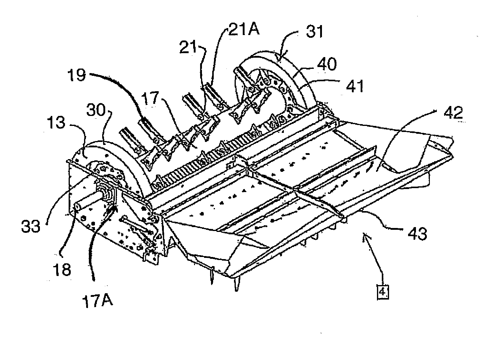
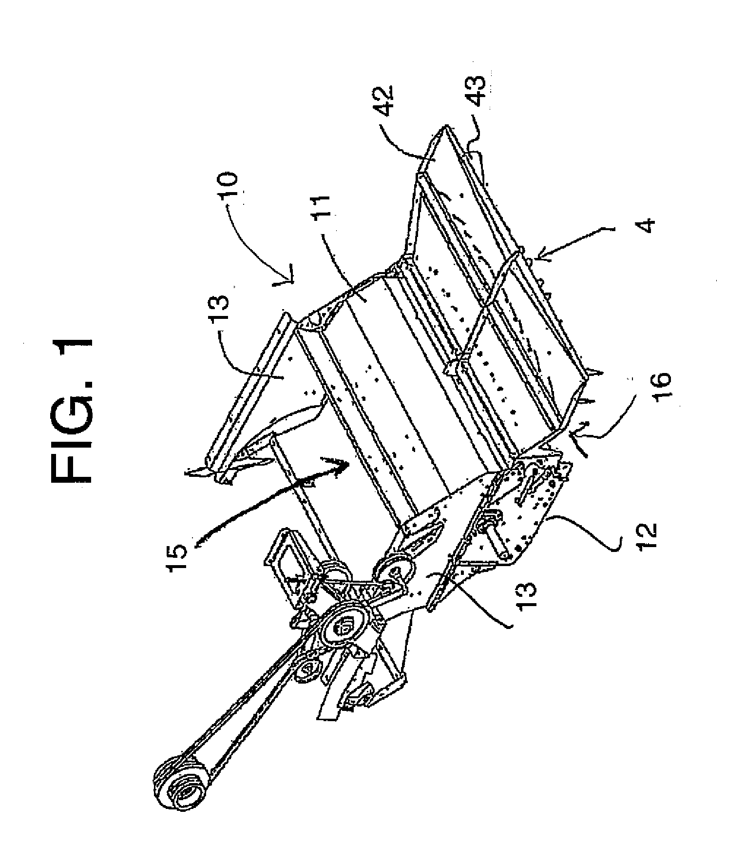
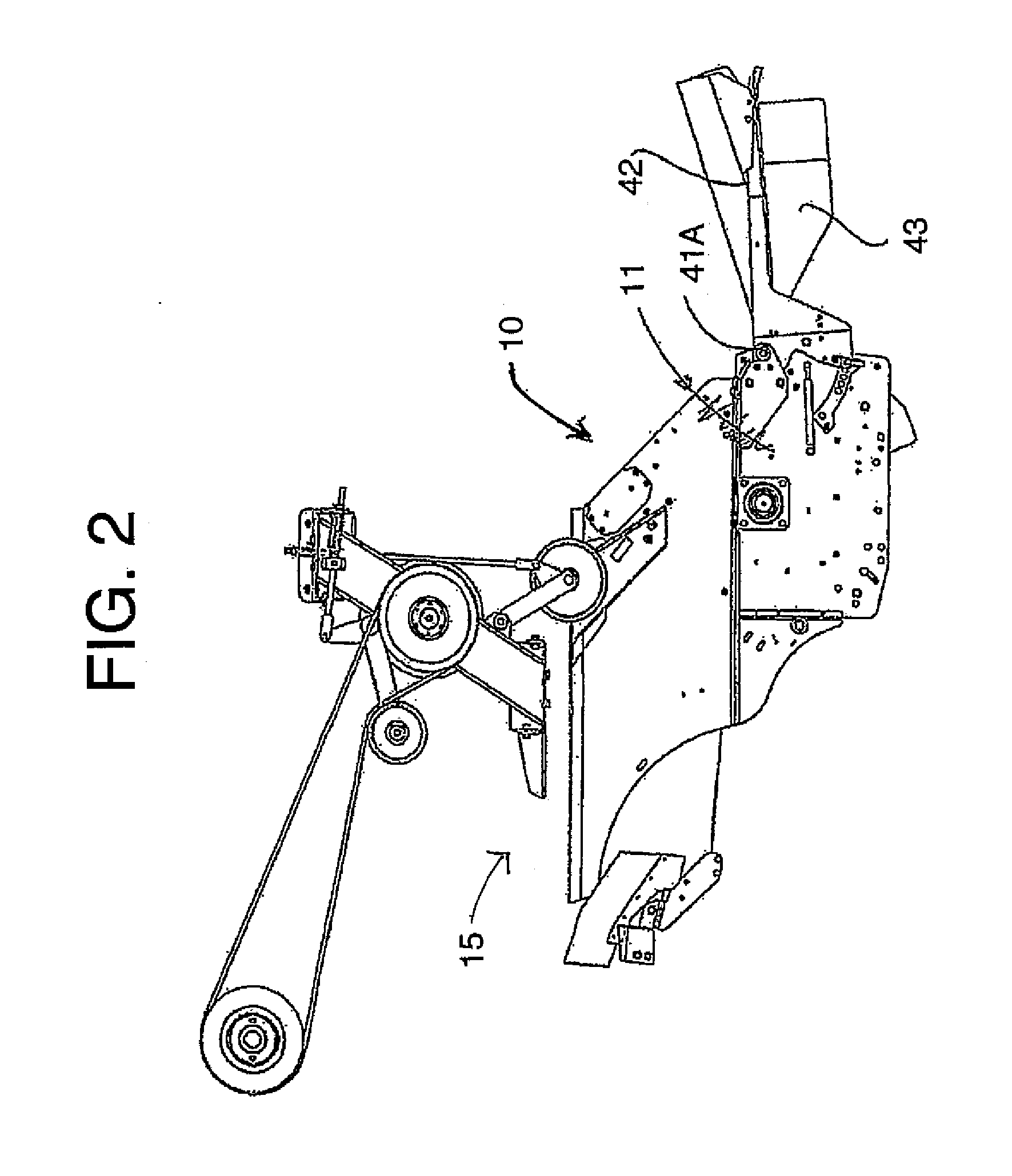
[0063]The chopper and discharge arrangement shown in FIGS. 1 to 4 is very similar to that from the prior patents of Redekop which are U.S. Pat. Nos. 5,232,405 and 5,482,508.

[0064]The apparatus which is basically as shown in U.S. Pat. No. 6,840,854 issued Jan. 11, 2005 of Redekop therefore comprises a housing 10 defined by a top wall 11, a bottom wall 12 and two side walls 13. The side walls 13 include attachment means schematically for attachment of the housing to the outlet of a combine harvester for discharge of straw and possibly chaff from the combine harvester into an inlet opening 15 of the housing 10. The bottom wall 12 defines a semi-cylindrical portion extending from the inlet 15 to an outlet 16 through which chopped straw and air is discharged at relatively high velocity for spreading across the field or for transportation into a container.

[0065]Within the housing is mounted a hub 17 which is carried on bearings 17A for rotation about a hub axis 18 at a center of the housi...


PUM


Abstract

A straw chopper to be mounted at the rear discharge of a combine harvester includes a housing with a feed opening and a discharge opening with a rotor mounted in the housing for chopping and accelerating the crop materials. The rotor has a hub and a plurality of flail blade members where at least some of the blades are formed of a plate having a mounting hole through the plate for mounting on a bushing or pin of the rotor where a bearing surface of the mounting hole of the plate and not the plate surface is coated with material such as tungsten carbide or chromium carbide of a thickness less than 0.020 inches which is harder than a parent material of the plate.

Description

[0001]This application claims the benefit under 35 USC 119(e) of Provisional Application 62 / 068109 filed Oct. 24, 2014.[0002]This invention relates to a cutting blade for example for use in an apparatus for chopping and discharging straw from a combine harvester.BACKGROUND OF THE INVENTION[0003]Many cutting machines use different styles of cutting blades which are free to pivot about their mounting hole. The blades operate in abrasive environments cutting residue, and wearing out quickly. Corn headers utilize cutting blades as shown in U.S. Pat. No. 8,402,727. Forage mowers utilize blades as shown in U.S. Pat. No. 8,307,620. Blade mowers utilize large swinging blades as shown in U.S. Pat. No. 5,626,007. Flail mowers use blades as shown in U.S. Pat. No. 7,930,872.[0004]Combine harvesters harvest cereal grain crops, such as wheat, oats, rye, barley, corn, soybeans and flax. Grain and straw are separated in a combine harvester. Following the separation process, waste straw and chaff is...

Claims


Application Information

Patent Timeline
Patent Type & Authority Applications(United States)
IPC IPC(8): A01F12/40A01D41/12
CPCA01D41/1243A01F12/40A01D75/10A01F29/04A01F29/095
Inventor MAYERLE, DEAN
Owner MAYERLE DEAN
Why Eureka
Try Eureka