Water treatment system, water treatment method, cooling facility and power generating facility

a technology for water treatment systems and cooling facilities, applied in water/sewage multi-stage treatment, water treatment methods, other chemical processes, etc., can solve problems such as reducing treatment capacity

Inactive Publication Date: 2016-04-28
MITSUBISHI HEAVY IND ENG LTD
View PDF3 Cites 29 Cited by
  • Summary
  • Abstract
  • Description
  • Claims
  • Application Information

AI Technical Summary

Benefits of technology

[0030]According to the present invention, water to be treated containing at least a salt and silica, such as cooling tower blowdown water from a cooling tower used in a plant facility or the like can be reclaimed and reused.

Problems solved by technology

When scale is generated inside the apparatus for performing the desalination treatment described above, the treatment capacity is diminished.

Method used


Image

  • Water treatment system, water treatment method, cooling facility and power generating facility
  • Water treatment system, water treatment method, cooling facility and power generating facility
  • Water treatment system, water treatment method, cooling facility and power generating facility

Examples


embodiment 1

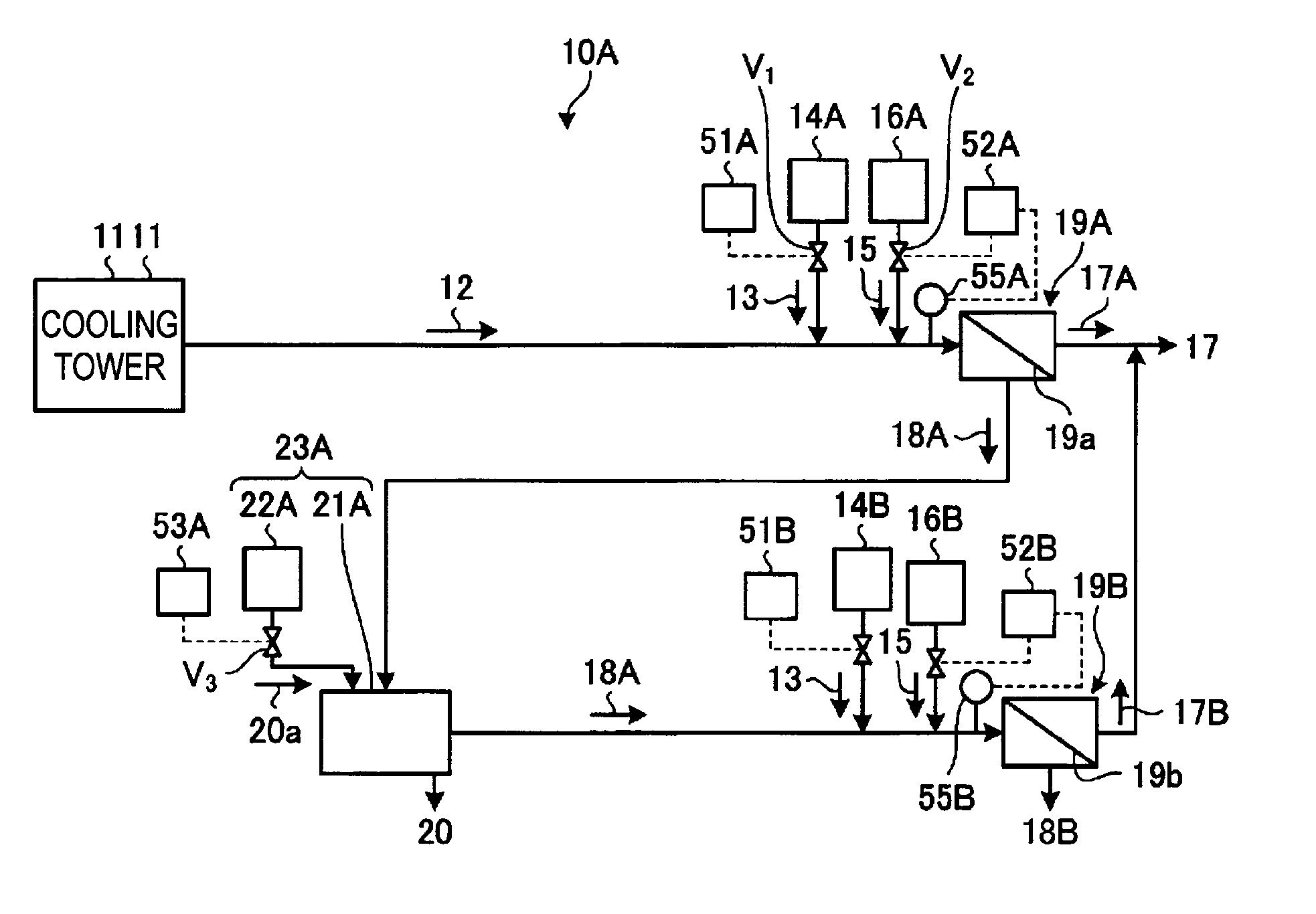
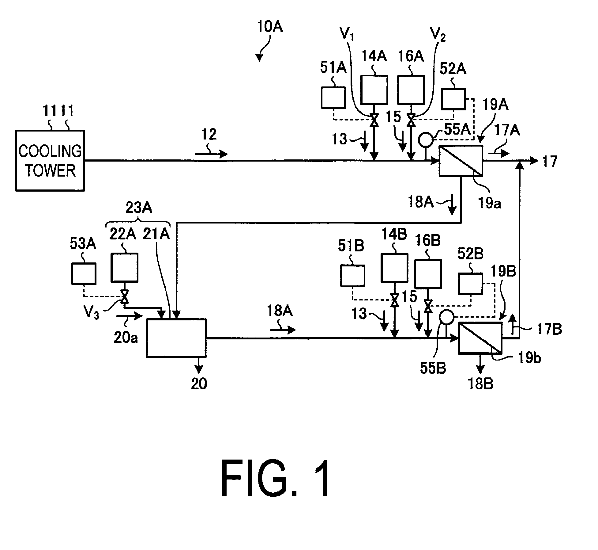
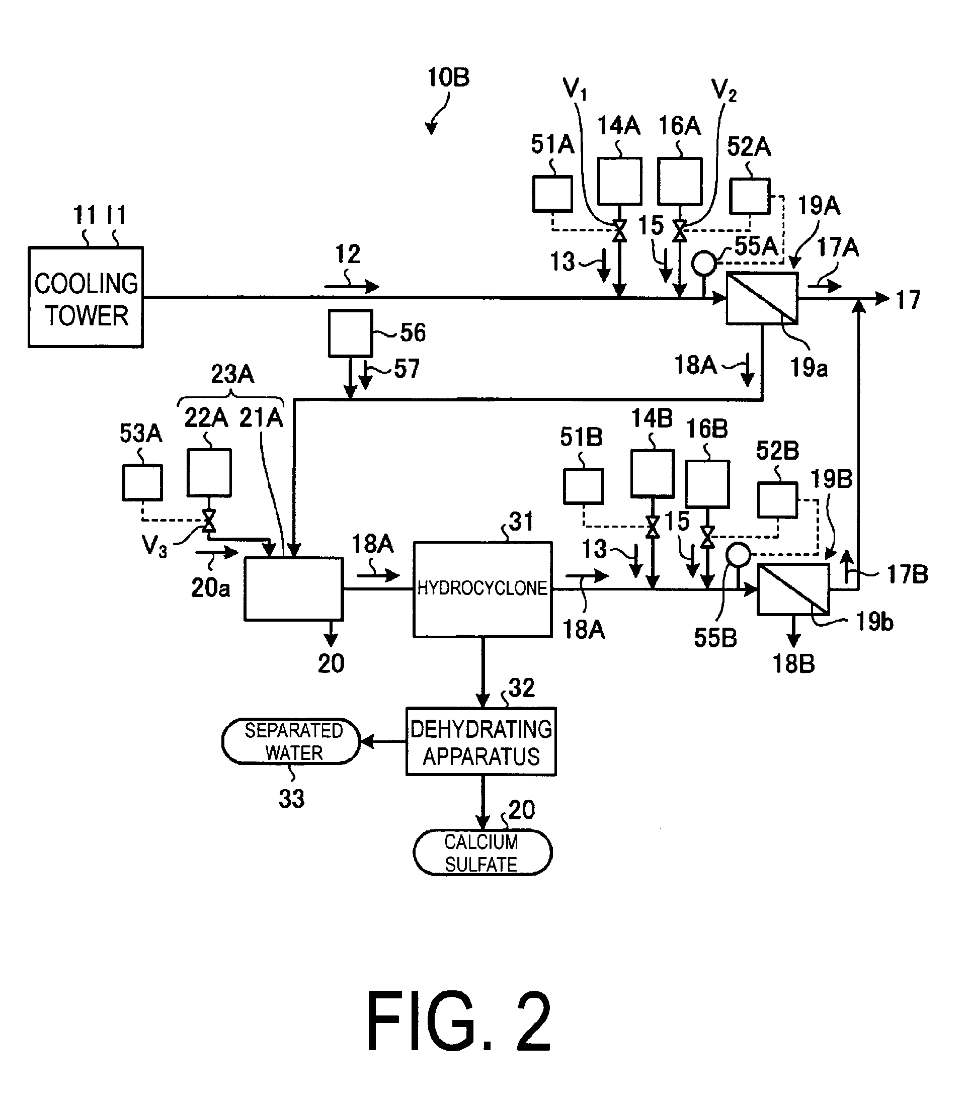
[0047]FIG. 1 is a schematic view of a cooling tower blowdown water reclamation treatment system pertaining to Embodiment 1. FIGS. 2 and 3 are schematic views of other cooling tower blowdown water reclamation treatment systems pertaining to Embodiment 1.

[0048]As illustrated in FIG. 1, a cooling tower blowdown water reclamation treatment system 10A pertaining to the present embodiment has a first scale inhibitor-supplying unit 14A, which supplies a scale inhibitor 13 to cooling tower blowdown water (“blowdown water” hereinafter), which is water to be treated, that contains at least a salt and silica and is generated by a cooling tower 11; a first pH-adjusting unit 16A, which adjusts a pH of blowdown water 12 to which the scale inhibitor 13 has been supplied using a pH-adjusting agent 15; a first desalinating apparatus 19A, which is provided downstream of the first pH-adjusting unit 16A, removes salts in the blowdown water 12 and separates the water into first reclaimed water 17A and f...

embodiment 2

[0131]Next, a cooling tower blowdown water reclamation treatment system pertaining to Embodiment 2 will be described. FIG. 4 is a schematic view of a cooling tower blowdown water reclamation treatment system pertaining to the present embodiment. As illustrated in FIG. 4, a cooling tower blowdown water reclamation treatment system 10D is the Embodiment 1 illustrated in FIG. 1 further comprising, as pretreatment, the degassing unit 61, which degasses carbonate ions in the blowdown water 12, a first settling unit 63A having a first adding unit 62A, which settles ions, and a first filtering apparatus 64A. Additionally, on the downstream side of first and second crystallizing units 23A and 23B, the cooling tower blowdown water reclamation treatment system 10D has second and third settling units 63B and 63C having second and third adding units 62B and 62C, which settle ions, and second and third filtering apparatuses 64B and 64C.

[0132]Also, as desalination treatment units, three-stage des...


PUM

PropertyMeasurementUnit
pHaaaaaaaaaa
pHaaaaaaaaaa
concentrationaaaaaaaaaa

Abstract

A water treatment system provided with: a first scale inhibitor-supplying unit which supplies a scale inhibitor to a blowdown water, the blowdown water being water to be treated that is generated in a cooling tower and contains at least a salt and silica; a first pH-adjusting unit which adjusts the pH of the blowdown water, to which the scale inhibitor has been supplied using a pH adjusting agent; a first desalinating apparatus which is provided downstream of the first pH-adjusting unit, removes the salt in the blowdown water, and separates the water into a first reclaimed water and a first concentrated water; and a first crystallizing unit which is provided downstream of the first desalinating apparatus and has a first crystallizing tank for calcium sulfate from the first concentrated water and a first seed crystal-supplying unit for supplying calcium sulfate seed crystals of calcium sulfate to the first crystallizing tank.

Description

TECHNICAL FIELD[0001]The present invention relates to a water treatment system and method for, for example, cooling tower blowdown water or the like, a cooling facility, and a power generating facility.BACKGROUND ART[0002]In a cooling tower used at a plant facility or the like, heat exchange is performed between cooling water and high-temperature exhaust gas discharged from a boiler or the like. A portion of the cooling water becomes steam due to this heat exchange, so the ions or silica (SiO2) in the cooling water are concentrated. Accordingly, the cooling water discharged from the cooling tower (blowdown water) reaches a state with a high ion concentration or silica concentration.[0003]Water containing large quantities of ions is released into the environment after being desalinated. Known examples of apparatuses for performing desalination treatment include a reverse osmosis membrane apparatus, a nanofiltration membrane apparatus, and an ion exchange membrane apparatus.[0004]Of t...

Claims


Application Information

Patent Timeline
Patent Type & Authority Applications(United States)
IPC IPC(8): C02F9/00
CPCC02F9/00C02F1/66C02F2001/5218C02F1/5281C02F2103/023C02F2001/007C02F1/441C02F1/58C02F5/08C02F1/04C02F1/20C02F1/42C02F5/10B01D9/0036C02F1/004C02F1/442C02F1/4691C02F1/4693C02F1/4695C02F1/5245C02F5/086C02F5/14C02F2209/01C02F2209/06C02F2301/08C02F2303/22Y02A20/131Y02A20/124
Inventor UKAI, NOBUYUKIOKINO, SUSUMUEDA, MASAYUKISUZUKI, HIDEONAKASHOJI, HIROSHIYOSHIOKA, SHIGERU
Owner MITSUBISHI HEAVY IND ENG LTD
Why Eureka
Try Eureka