Geometric-error identification system and geometric-error identification method

a technology of geometric errors and identification systems, applied in the direction of speed/acceleration/shock measurement devices, surveying and navigation, testing/calibration, etc., can solve the problems of affecting the motion accuracy, the accuracy of geometric errors is not always accurate, and the subsequent calibration is not often performed. to achieve the effect of improving the accuracy of identifying geometric errors, improving the positioning accuracy of the machine, and facilitating calibration

Inactive Publication Date: 2016-04-28
OKUMA CORP
View PDF2 Cites 19 Cited by
  • Summary
  • Abstract
  • Description
  • Claims
  • Application Information

AI Technical Summary

Benefits of technology

[0012]The present invention allows performing calibration of the position measurement sensor such as a touch trigger probe using the initial measurement value acquired to measure the initial position of the measurement object jig, so as to perform calibration of the position measurement sensor simultaneously with measurement of the initial position. According

Problems solved by technology

In this multi-axis machine tool, geometric errors between the respective axes, for example, the error of the center position in the rotation axis and the tilt error (the perpendicularity and the parallelism between the axes) of the rotation axis are factors affecting the motion accuracy.
The offset is also caused by misalignment between the main spindle center and the touch trigger probe, signal delay during contact into the target ball, the sensor characteristics

Method used


Image

  • Geometric-error identification system and geometric-error identification method
  • Geometric-error identification system and geometric-error identification method
  • Geometric-error identification system and geometric-error identification method

Examples


Embodiment Construction

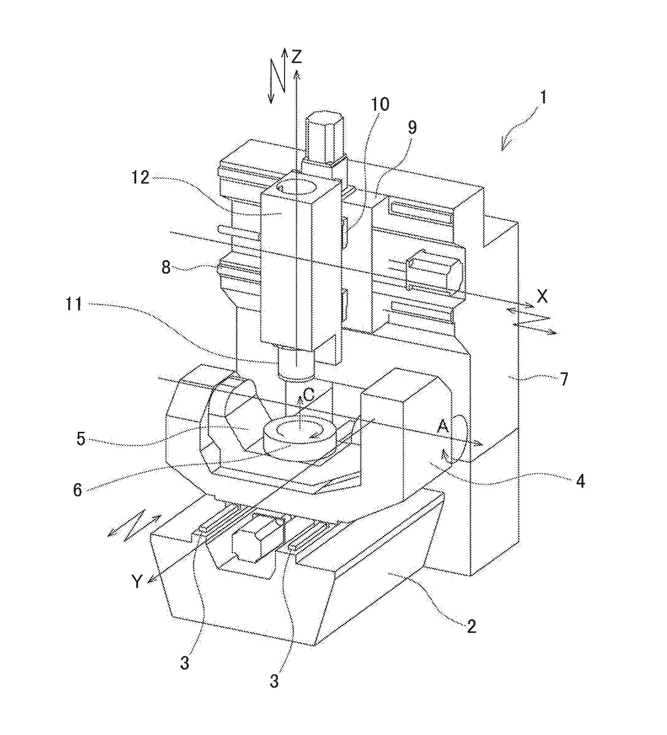
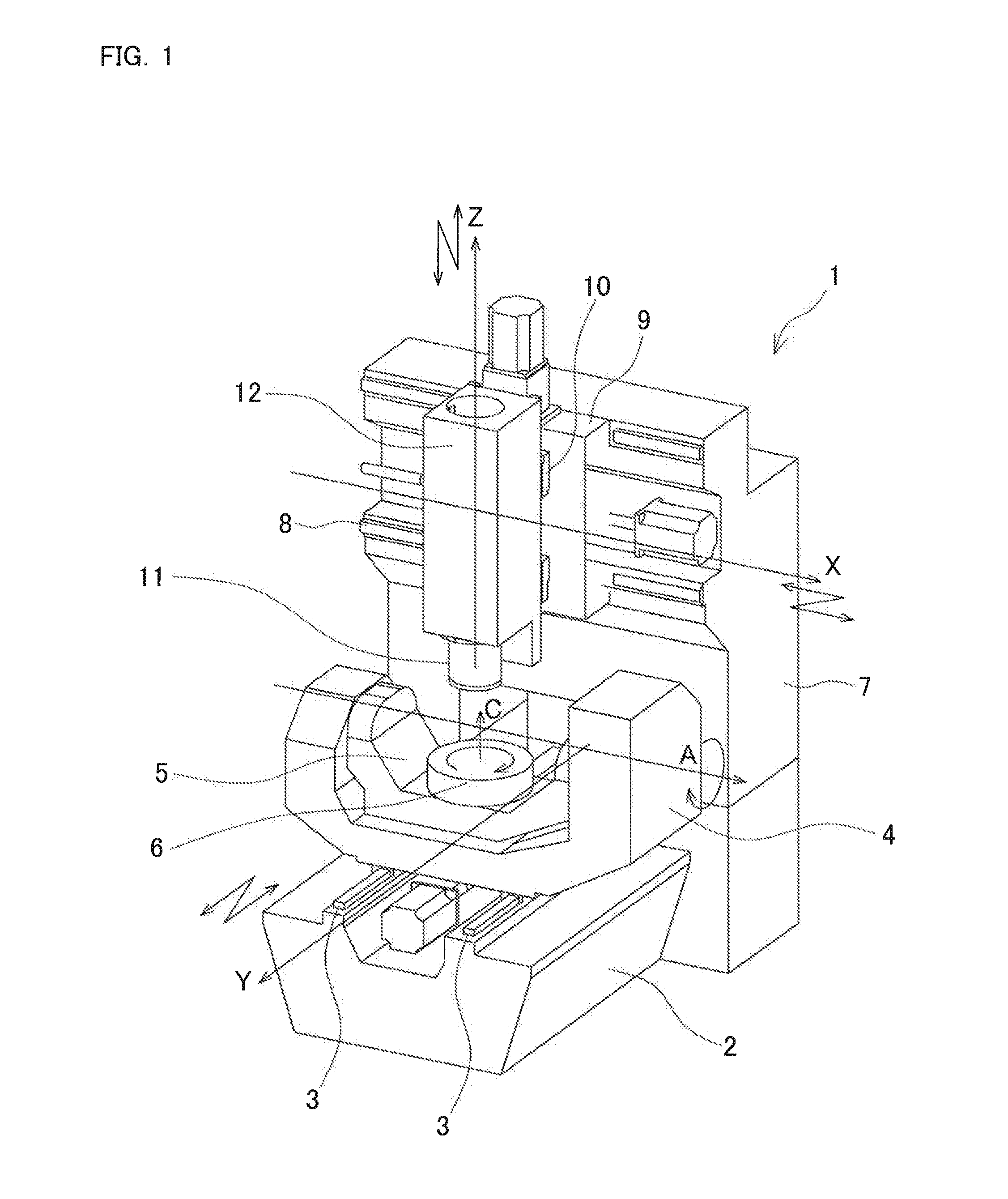
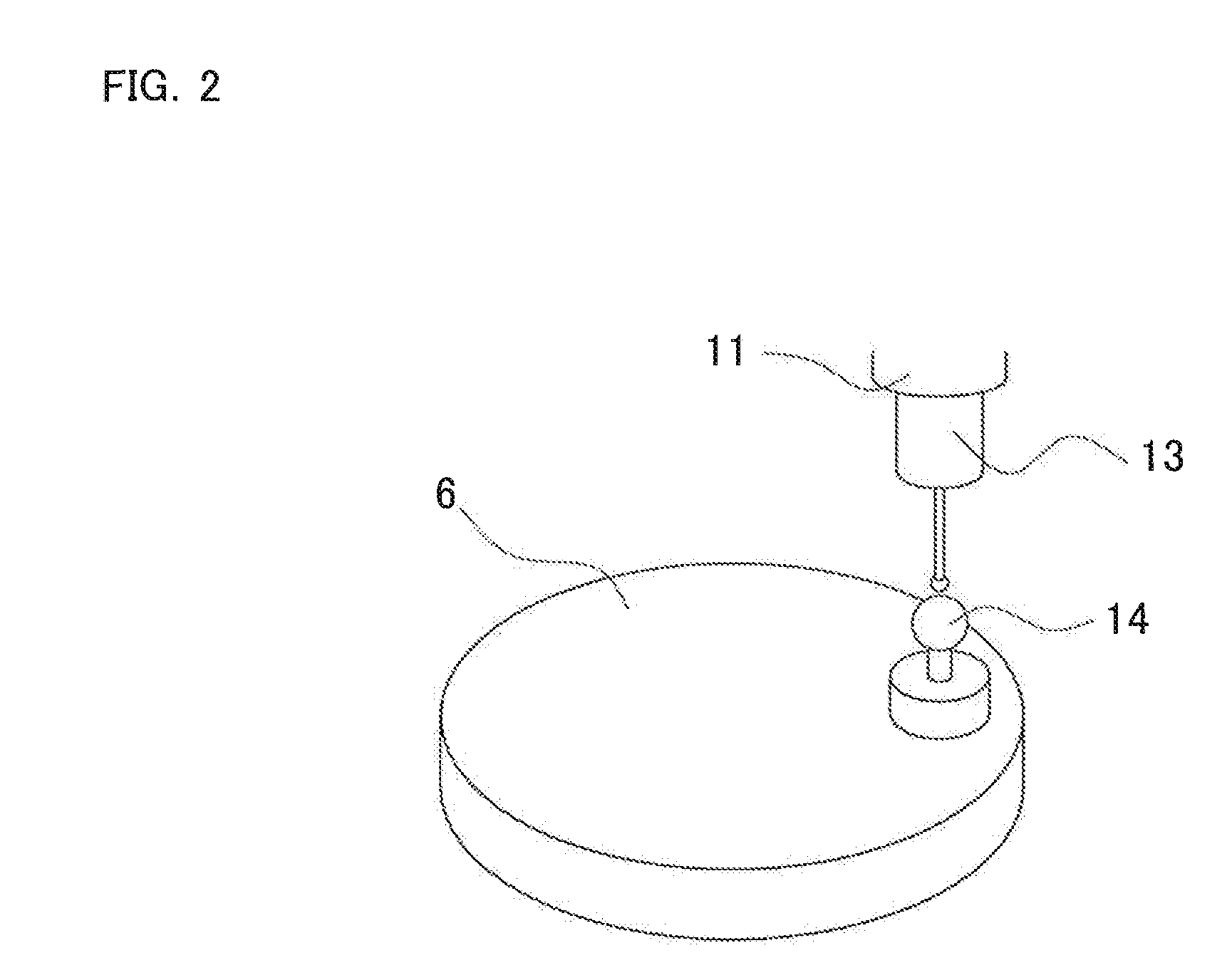
[0019]The following describes geometric-error identification system and method as one embodiment of the present invention in detail based on the drawings. Here, in this embodiment, a description will be given of identification of geometric errors in a five-axis control machining center as one example of a machine that includes a translational axis and a rotation axis.

[0020]Firstly, a description will be given of a multi-axis machine tool 1 based on FIG. 1. FIG. 1 is a perspective explanatory view illustrating the multi-axis machine tool 1. Here, the X-axis, the Y-axis, and the Z-axis in FIG. 1 are orthogonal three axes (the translational axes provided in the multi-axis machine tool 1). Assuming that the Y-axis direction is the front-back direction in the multi-axis machine tool 1, the X-axis direction is the right-left direction, and the Z-axis direction is the above-below direction.

[0021]On the top surface of a bed 2 of the multi-axis machine tool 1, Y-axis guides 3 and 3 are forme...


PUM


Abstract

A geometric-error identification system includes a control unit configured to identify geometric errors in a machine. The machine controls three or more translational axes and one or more rotation axes so as to perform positioning for a positional relationship between a main spindle and an object. The control unit controls the rotation axis so as to index a measurement object jig, measures an indexed position of the indexed measurement object jig on a three-dimensional space using a position measurement sensor attached to the main spindle so as to acquire a measurement value, and identifies geometric errors of the machine related to the translational axis and/or the rotation axis based on the measurement values in a plurality of positions. The control unit measures an initial position of the measurement object jig and performs calibration of the position measurement sensor using an initial measurement value acquired for measuring the initial position.

Description

BACKGROUND[0001]This application claims the benefit of Japanese Patent Application Number 2014-218476 filed on Oct. 27, 2014 the entirety of which is incorporated by reference.TECHNICAL FIELD[0002]The present invention relates to a geometric-error identification system and a geometric-error identification method for identifying a geometric error in a machine that includes a translational drive axis and a rotational drive axis.RELATED ART[0003]Conventionally, there is a multi-axis machine tool as a machine that includes a translational drive axis and a rotational drive axis. For example, the multi-axis machine tool disclosed in Japanese Patent Application Publication No. 2011-38902 (JP-A-2011-38902) controls the operations in the five axial directions in total, which include the C-axis and the A-axis as the rotation axes on a table side in addition to the X-axis, the Y-axis, and the Z-axis as the orthogonal three axes, to perform processing. In this multi-axis machine tool, geometric...

Claims


Application Information

Patent Timeline
IPC IPC(8): G01B21/04
CPCG01B21/042
Inventor MATSUSHITA, TETSUYAOKI, TADAHIRO
Owner OKUMA CORP
Why Eureka
Try Eureka