Head worn displaying device employing mobile phone

a mobile phone and display device technology, applied in the field of head worn display devices, can solve the problems of difficult to achieve a large field of view (fov), limited resolution and high cost of micro displaying modules used in head worn displays based on augmented reality (ar) technology, etc., to achieve a large fov and deep immersion experience, simple structure, and light weight

Active Publication Date: 2016-04-28
TAPUYIHAI SHANGHAI INTELLIGENT TECH CO LTD
View PDF11 Cites 27 Cited by
  • Summary
  • Abstract
  • Description
  • Claims
  • Application Information

AI Technical Summary

Benefits of technology

[0013]Apparently, the disclosed head worn displaying device has a large FOV and deep sense of immersion given a large display screen and near eye magnified virtual images. The simple structure mean

Problems solved by technology

In the prior art, not only a micro displaying module used in a head worn display based on augmented reality (AR) technology is expensive, but also the resolution of the micro displaying module is limited.
In addition, in the most of the see-through head worn displaying devices, one reflecting display module only serves a single eye, and it is difficult to achieve a large field of view (FOV) due to a limited aperture or a serious image distortion given large off axis angles.
Therefore, more intermediate optical modules are needed to expand the FOV and reduce the distortion, which results in an increase of cost, weight and volume of the HMD.
Therefore, it is

Method used


Image

  • Head worn displaying device employing mobile phone
  • Head worn displaying device employing mobile phone
  • Head worn displaying device employing mobile phone

Examples


Embodiment Construction

[0024]The disclosure is illustrated by way of example and not by way of limitation in the figures of the accompanying drawings, in which like reference numerals indicate similar elements. It should be noted that references to “an” or “one” embodiment in this disclosure are not necessarily to the same embodiment, and such references can mean “at least one” embodiment.

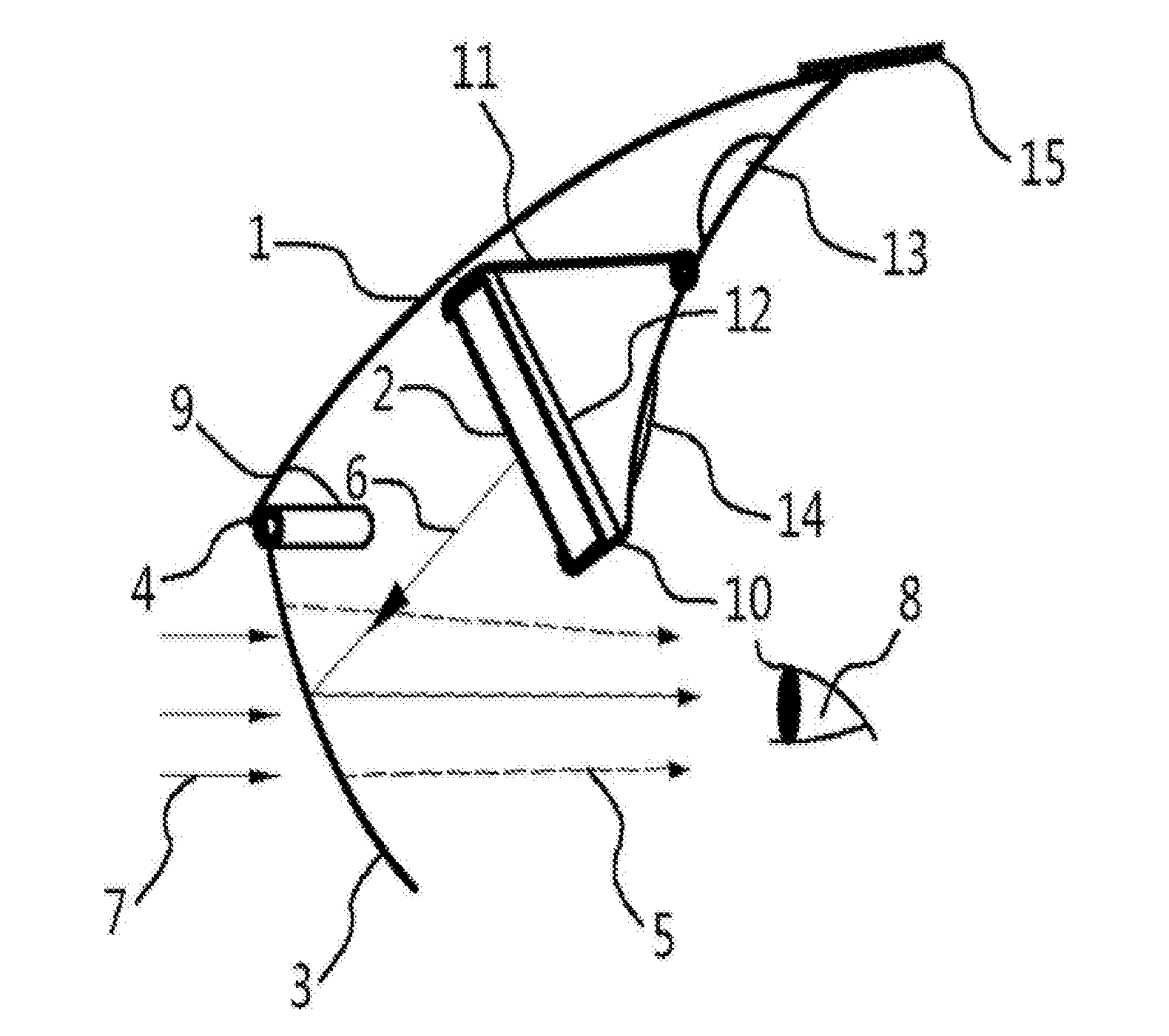
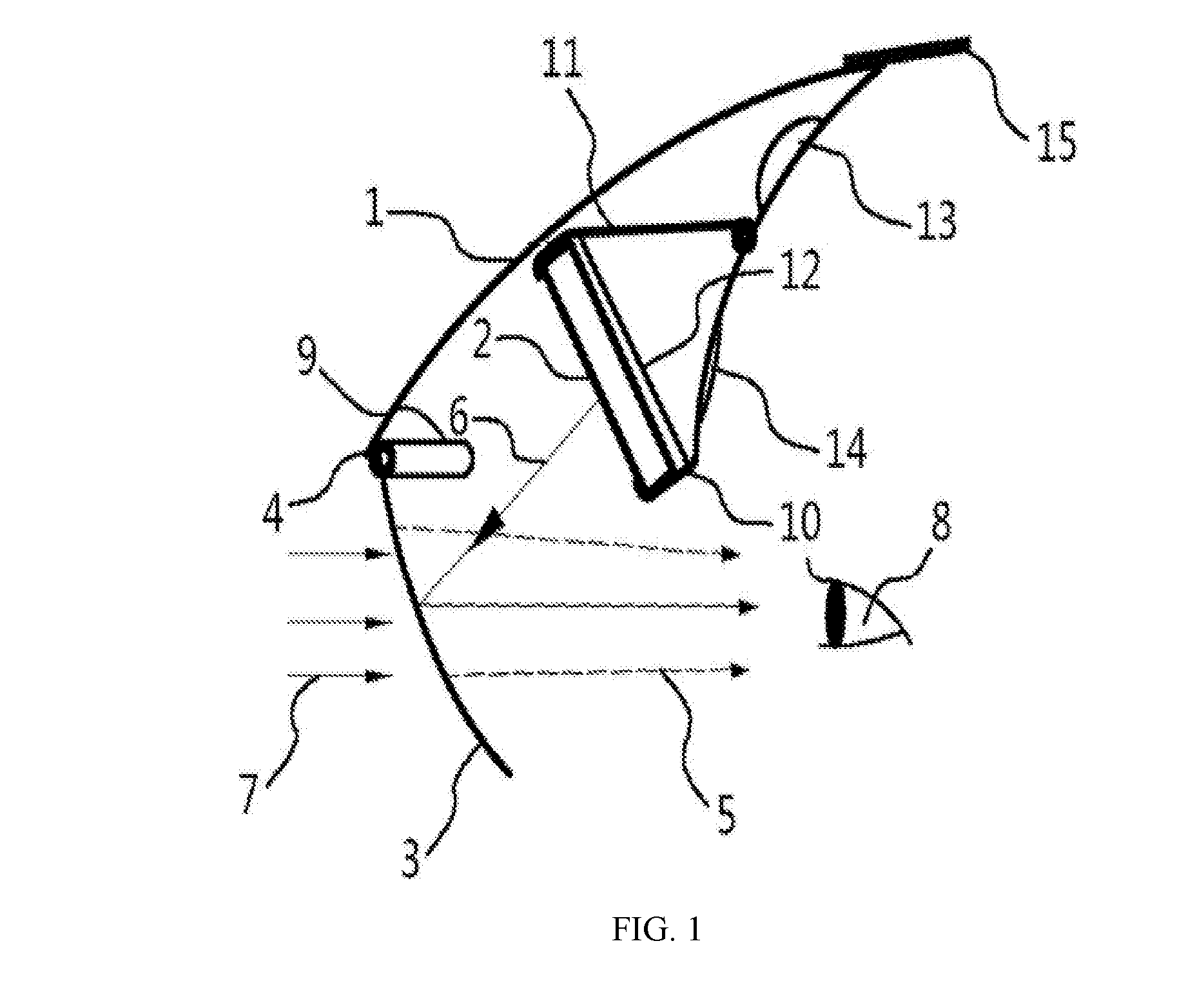
[0025]With reference to FIG. 1, the head worn displaying device of the disclosure includes a hat tongue 1 located ahead of the forehead of a user, a clamper set (10, 11, 12) for clamping a mobile phone 2, and an optical lens 3. In some typical embodiments, the display screen 21 of the mobile phone 2 may have a diagonal size of about 3 to 6 inches, and the optical lens 3 may have a height up to 100 mm and a width up to 200 mm to enable a large FOV. In general, the hat tongue 1 may be replaced by any piece of light material that can cover the display screen 21 and at least partially block the stray light from the upper sid...


PUM


Abstract

A head worn displaying device of the disclosure includes an optical reflective lens, a display screen and a cover. The optical lens and the display screen are mounted under the cover, and the cover may be similar to a hat tongue located ahead of the forehead of a user. The display screen can be integrated in a mobile phone, and a holder such as a clamper set is used to clamp the mobile phone. The angle of the optical lens can be adjusted, for example, by using a sliding groove and a magnetic hinge which are located at a front end of the hat tongue. The magnetic hinge slides in the sliding groove to adjust a distance between the display screen and the optical lens. The light rays of the display screen will be reflected by the optical lens to form virtual magnified images with reduced distortions for both eyes at the same time, and the optical lens optically combines the reflected virtual images with and external environmental light rays transmitted through the optical lens to form the augmented reality for the eyes.

Description

CROSS-REFERENCE TO RELATED APPLICATIONS[0001]This application is a continuation of and claims benefit of the following patent properties: U.S. provisional patent application Ser. No. 62 / 068,056, filed on Oct. 24, 2014, the above application is hereby incorporated by reference herein as if set forth in its entirety.BACKGROUND[0002]1. Technical Field[0003]The present disclosure generally relates to head worn displaying devices, or head mounted displays (HMD), especially to a head worn see-through displaying device employing a reflecting free form curved surface and an image source provided by a large display screen such as generally used in a mobile phone.[0004]2. Description of Related Art[0005]In the prior art, not only a micro displaying module used in a head worn display based on augmented reality (AR) technology is expensive, but also the resolution of the micro displaying module is limited. In addition, in the most of the see-through head worn displaying devices, one reflecting ...

Claims


Application Information

Patent Timeline
IPC IPC(8): G02B27/01G02F1/1335H04R1/46G02B27/00G06F3/16G06F3/01G02F1/13G02F1/136
CPCG02B27/0172H04R2499/15G02F1/1313G02F1/133555G02F1/136G02B27/0093G06F3/167G06F3/011H04R1/46G02B2027/011G02B2027/0169G02B2027/0154G02B2027/0161G02B2027/013G02B2027/014G02B2027/0123G02B27/0176G06F1/163G06F3/012H04R2460/13
Inventor WEI, RONGJIE
Owner TAPUYIHAI SHANGHAI INTELLIGENT TECH CO LTD
Why Eureka
Try Eureka