USB power supply apparatus

a power supply apparatus and usb technology, applied in the direction of power conversion systems, instruments, dc-dc conversion, etc., can solve the problems of high cost of mosfets and the same problem can occur in usb type-c specifications, and achieve the effect of suppressing voltage drop

Active Publication Date: 2016-04-28
ROHM CO LTD
View PDF5 Cites 19 Cited by
  • Summary
  • Abstract
  • Description
  • Claims
  • Application Information

AI Technical Summary

Benefits of technology

[0015]The present invention has been made in view of such a situation. Accordingly, it is an exemplary purpose of an embodiment of the present invention to provide a USB power supply apparatus that is capable of suppressing voltage drop that occurs in the bus voltage output from a receptacle.
[0017]With such an embodiment, the feedback point set for the power supply circuit can be switched according to the state of the USB power supply apparatus. Such an arrangement reduces an amount of voltage drop that occurs in the bus voltage with respect to the setting voltage thereby providing improved line regulation.
[0022]Also, a receptacle into which a USB cable is to be inserted may be provided to an end of a cable. Also, the selector may receive, as its input signals, the output voltage of the power supply circuit and the bus voltage at the end of the cable. Such an arrangement is capable of eliminating the effect of voltage drop that occurs in the internal components included within the cable.

Problems solved by technology

However, a MOSFET having an on resistance of several mΩ is costly.
The same problem can occur in the USB Type-C specification.

Method used


Image

  • USB power supply apparatus
  • USB power supply apparatus
  • USB power supply apparatus

Examples


first modification

[First Modification]

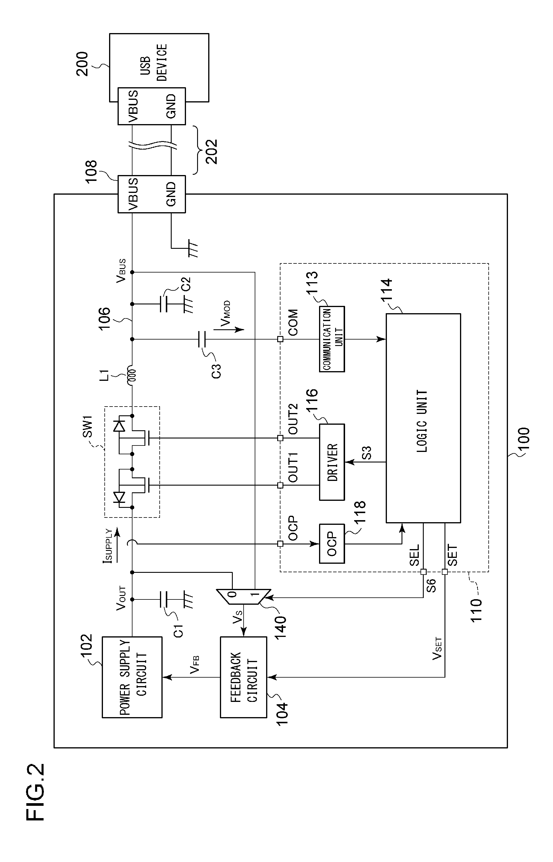
[0070]Description will be made in the embodiment regarding an arrangement in which the selector 140 selects the bus voltage VBUS during a period in which the switch SW1 is in the on state. However, the present invention is not restricted to such an arrangement. Also, the controller 110 may control the selector 140 based on the supply current ISUPPLY during a period in which the switch SW1 is in the on state. For example, when the supply current ISUPPLY is larger than a predetermined threshold value, i.e., when the voltage drop VDROP is large, the controller 110 may instruct the selector 140 to select the bus voltage VBUS so as to stabilize the bus voltage VBUS in the vicinity of the setting voltage VSET. Conversely, when the supply current ISUPPLY is smaller than the threshold value, i.e., when the voltage drop VDROP is small, the controller 110 may instruct the selector 140 to select the output voltage VOUT.

second modification

[Second Modification]

[0071]FIG. 5 is a perspective view of a USB power supply apparatus 100a according to a second modification. The receptacle 108 is provided to one end of a cable 150 instead of being provided to a casing 101 of the USB power supply apparatus 100a. The cable 150 is provided with a feedback line 152 in addition to the bus line 106 and a ground line 107. One end of the feedback line 152 is connected in the vicinity of a connection node that connects the bus line 106 and the receptacle 108. The feedback line 152 is used to detect the bus voltage VBUS at the end of the cable 150. The selector 140 receives, as its input signals, the output voltage VOUT of the power supply circuit 102 and the bus voltage VBUS at the end of the cable 150.

[0072]In a case in which the cable 150 does not include the feedback line 152 as a built-in component, the selector 140 receives, as its input signal, the bus voltage VBUS′ at the start point of the cable 150. In this case, the bus volta...

third modification

[Third Modification]

[0073]Description has been made in the embodiment regarding the USB power supply apparatus 100 that conforms to the USB-PD specification. Also, the present invention is applicable to an arrangement that conforms to the USB Type-C specification. FIG. 6 is a block diagram showing a USB power supply apparatus 100b according to a third modification. With the USB Type-C specification, a controller 110b and the power receiving apparatus 200 communicate with each other via a dedicated line 204. That is to say, the modulation voltage VMOD is not superimposed on the bus voltage VBUS. Thus, such an arrangement does not require the capacitor C3 shown in FIG. 2. Also, the inductor L1 may be omitted. The other configuration is the same as that shown in FIG. 2.


PUM


Abstract

A USB power supply apparatus conforms to the USB (Universal Serial Bus) specification, and supplies electric power to a USB power receiving apparatus. A bus line connects the output of a power supply circuit and the USB power receiving apparatus. A switch is provided on a path of the bus line. A selector selects one from among the output voltage VOUT of the power supply circuit and the bus voltage VBUS at a position that is closer to the USB power receiving apparatus side than the switch. A feedback circuit feedback controls the power supply circuit such that the voltage VS selected by the selector approaches a setting voltage VSET. A controller controls the switch and the selector based on the state of the USB power supply apparatus.

Description

[0001]This application is based upon and claims the benefit of priority under 35 U.S.C. §119 from the prior Japanese Patent Application No. 2014-217687, filed Oct. 24, 2014, the entire contents of which are incorporated herein by reference.BACKGROUND OF THE INVENTION[0002]1. Field of the Invention[0003]The present invention relates to a USB power supply apparatus.[0004]2. Description of the Related Art[0005]Battery-driven devices such as cellular phone terminals, tablet terminals, laptop computers, and portable audio players each include a chargeable secondary battery and a charger circuit that charges the secondary battery as built-in components. Known examples of such charger circuits include an arrangement that charges a secondary battery using a DC voltage (bus voltage VBUS) supplied from an external circuit via a USB (Universal Serial Bus) cable.[0006]At present, as a charger circuit mounted on a mobile device, charger circuits that conform to a specification which is referred ...

Claims


Application Information

Patent Timeline
Patent Type & Authority Applications(United States)
IPC IPC(8): H02M3/156H02M3/335
CPCH02M3/33523H02M3/156
Inventor MOTOKI, KENICHI
Owner ROHM CO LTD
Why Eureka
Try Eureka