Conditioned launch of a single mode light source into a multimode optical fiber

a single-mode light source and multi-mode technology, applied in the field of optical fiber networks, can solve the problems of increasing the complexity and cost of the transceiver packaging, the optical isolator may not have the desired effect, and the single-mode light source is more sensitive to back reflection, so as to avoid defects in the mmf, increase the bandwidth, and the link length.

Inactive Publication Date: 2016-05-05
AVAGO TECH WIRELESS IP SINGAPORE PTE
View PDF0 Cites 5 Cited by
  • Summary
  • Abstract
  • Description
  • Claims
  • Application Information

AI Technical Summary

Benefits of technology

[0009]The invention is directed to an optical transmitter module and methods that use a single mode light source and an MMF in a way that allows higher bandwidth and greater link length to be achieved while also controlling launch conditions to manage back reflection and avoid defects in the MMF. The optical transmitter comprises a single mode light source and an optical coupling system. The single mode light source produces a light beam that is received by the optical coupling system. The optical coupling system is configured to receive the light beam, convert the light beam into light having a preselected spatial intensity distribution pattern, and direct the light having the preselected spatial intensity distribution pattern toward an end face of the MMF. The preselected spatial intensity distribution pattern is preselected to avoid one or more areas in the MMF that are likely to contain defects when the light having the preselected spatial intensity distribution pattern travels through the MMF.

Problems solved by technology

However, single mode light sources are more sensitive to back reflection than multimode light sources.
The optical isolator may not have the desired effect if used with a laser light source that has a variable-polarization output beam, such as a vertical cavity surface emitting laser diode (VCSEL).
Using an angled fiber pigtail or fiber stub can increase the complexity and cost of the transceiver packaging.
Fiber imperfections that often cause DMD are center and edge defects in the refractive index profiles of MMFs.
Such defects are generally due to the nature of the processes that are used to manufacture the MMFs.

Method used


Image

  • Conditioned launch of a single mode light source into a multimode optical fiber
  • Conditioned launch of a single mode light source into a multimode optical fiber
  • Conditioned launch of a single mode light source into a multimode optical fiber

Examples


Embodiment Construction

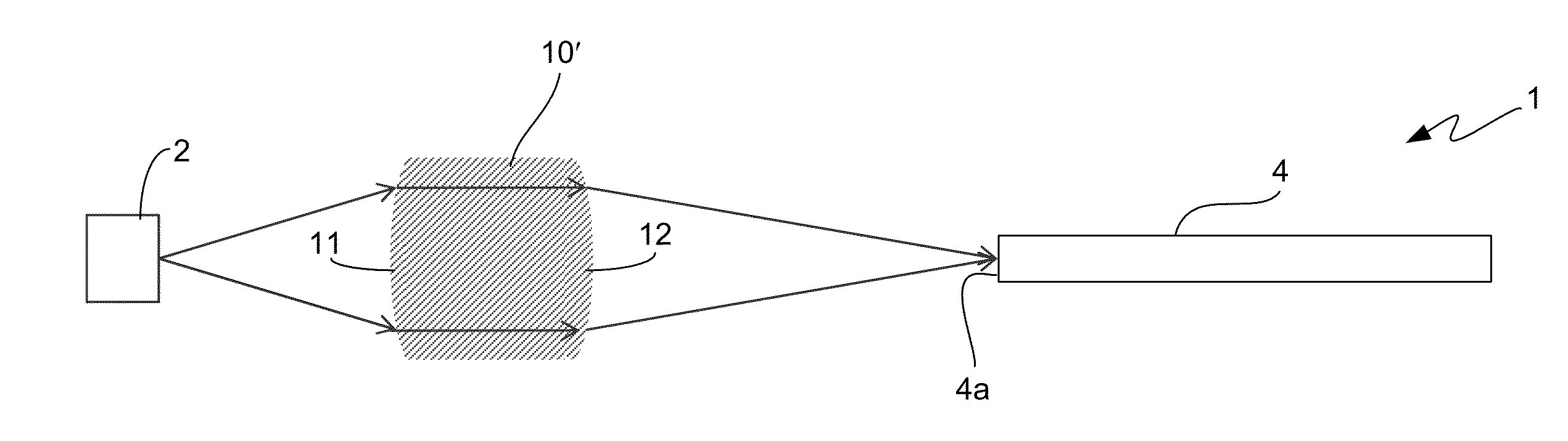
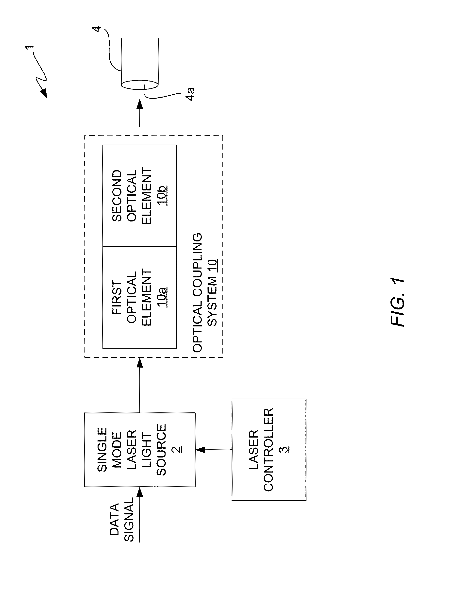
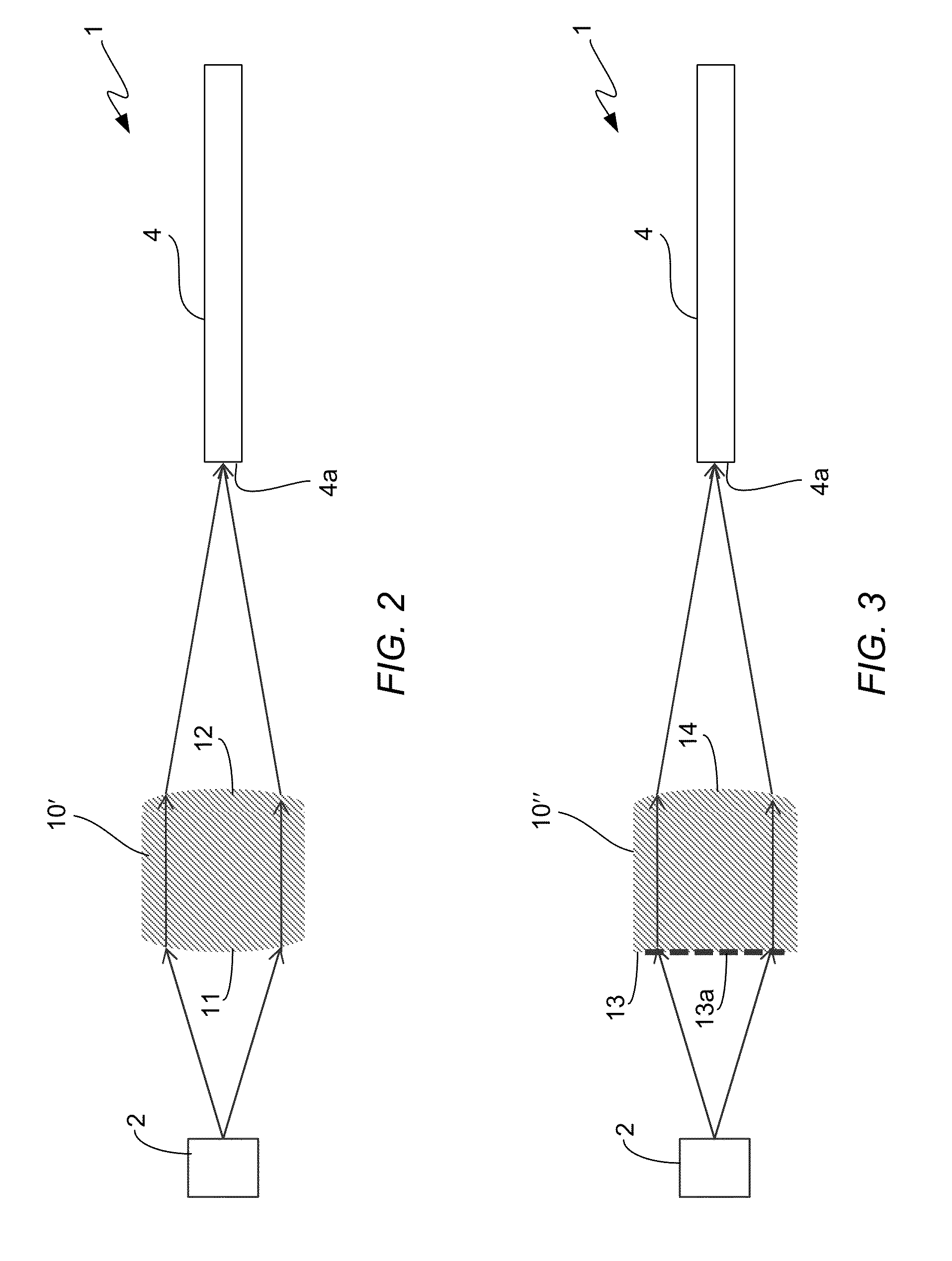
[0025]In accordance with the illustrative, or exemplary, embodiments described herein, an optical coupling system and method are provided for coupling light from a single mode laser (SML) light source into an MMF in a way that reduces back reflection of laser light into the SML light source and provides controlled launch conditions that allow the laser light to avoid defective areas in the MMF as the light travels through the MMF. The launch conditions are controlled to cause preselected spatial intensity distribution patterns to be launched into the MMF that cause the laser light to avoid defective areas in the MMF as the light passes through the MMF. The combination of these features allows greater link bandwidth and link length to be achieved with an MMF without increasing transceiver packaging complexity.

[0026]In accordance with one illustrative embodiment, the optical coupling system comprises a first optical element that reduces back reflection and a second optical element tha...


PUM


Abstract

An optical coupling system and method are provided for coupling light from a single mode laser (SML) light source into an MMF that reduce back reflection of laser light into the SML light source and provide controlled launch conditions that allow the light to avoid defective areas in the MMF as the light travels in the MMF. The launch conditions are controlled to cause preselected spatial intensity distribution patterns to be launched into the MMF that result in the laser light avoiding defective areas in the MMF as the laser light passes through the MMF. The combination of all of these features allows greater link bandwidth and link length to be achieved with an MMF without increasing transceiver packaging complexity. In addition, because the preselected spatial intensity distributions allow the light to avoid particular areas in the fiber that are likely to contain defects, fiber manufacturers can focus less on reducing defects in those areas and focus more on optimization of performance parameters.

Description

TECHNICAL FIELD OF THE INVENTION[0001]The invention relates to optical fiber networks and, more particularly, to using a single mode light source with a multimode optical fiber link to increase the bandwidth of the optical fiber link while also reducing back reflection and allowing the link length to be increased.BACKGROUND OF THE INVENTION[0002]In optical communications networks, optical transceiver modules are used to transmit and receive optical signals over optical fibers. A transceiver module includes a transmitter side and a receiver side. On the transmitter side, a laser light source generates modulated laser light and an optical coupling system receives the modulated laser light and optically couples, or images, the light onto an end of an optical fiber. The laser light source typically comprises one or more laser diodes that generate light of a particular wavelength or wavelength range. A laser diode driver circuit of the transmitter side outputs electrical drive signals th...

Claims


Application Information

Patent Timeline
Patent Type & Authority Applications(United States)
IPC IPC(8): G02B6/14G02B5/32G02B6/32G02B6/34H01S3/00G02B6/42
CPCG02B6/14H01S3/0064G02B6/4206G02B5/32G02B6/4255G02B6/32G02B6/34G02B6/4207G02B6/4286G02B6/4296G02B27/0916G02B27/4233
Inventor CHEN, YECHENG, AN-NIEN
Owner AVAGO TECH WIRELESS IP SINGAPORE PTE
Why Eureka
Try Eureka