

Component for a timepiece movement
a timepiece movement and component technology, applied in the field of components for timepiece movements, can solve the problems of limited hardness, inability to use moving components, and sensitive magnetic fields of material types, and achieve the effect of convenient machin
- Summary
- Abstract
- Description
- Claims
- Application Information
AI Technical Summary
Benefits of technology
Problems solved by technology
Method used
Image


Examples
Embodiment Construction
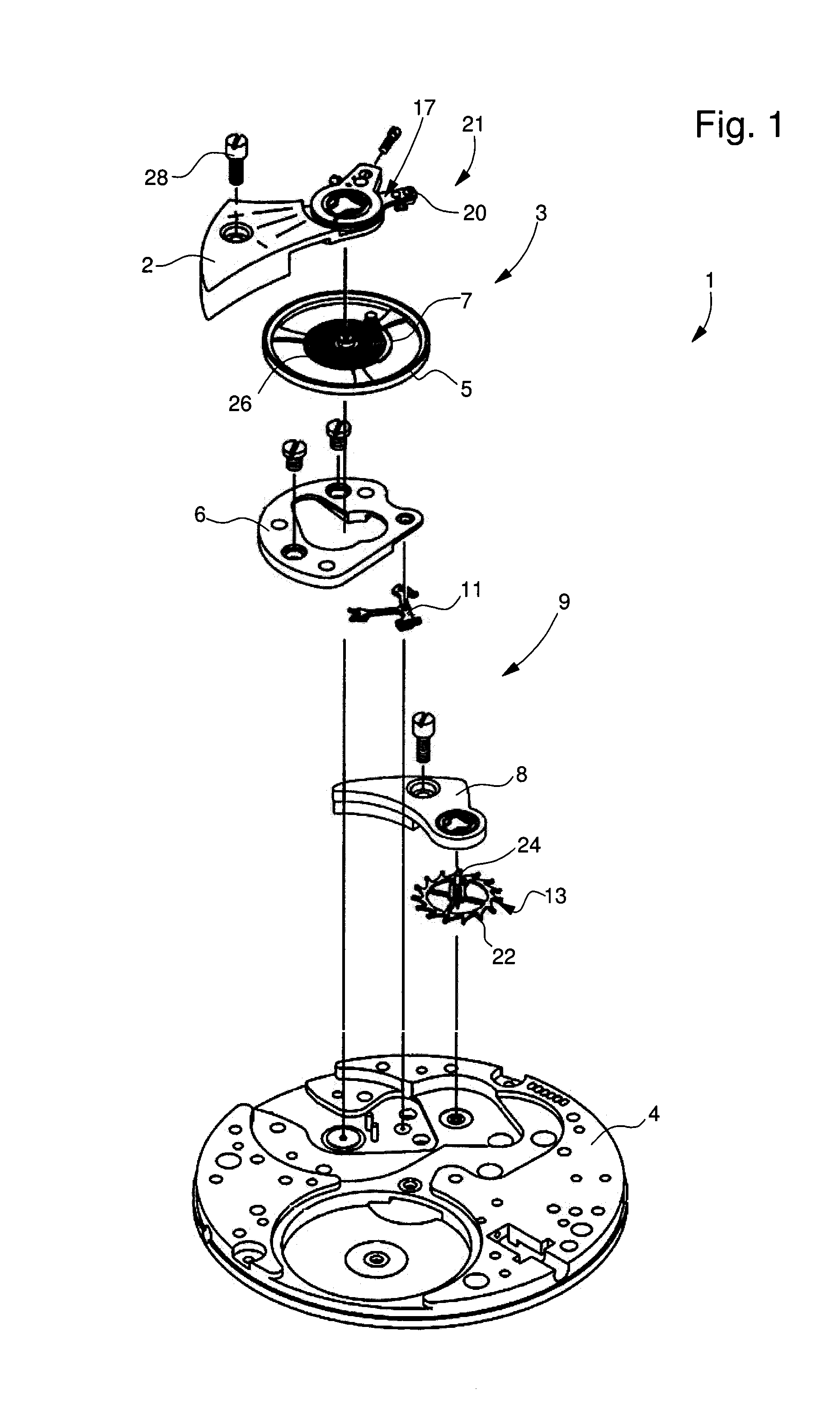
[0042]FIG. 1 shows a partial view of a timepiece movement 1 according to the invention, intended to be mounted in a timepiece. Movement 1 preferably includes a resonator 3 comprising a balance 5 and a balance spring 7 for regulating movement 1. Resonator 3 is preferably mounted to pivot notably by means of a collet 26 of balance spring 7 mounted on an arbor, between a bridge 2 and a main plate 4 and includes an index system 21 mounted on bridge 2 mainly comprising an index 17. It can be seen in FIG. 1 that bridge 2 is fixed to main plate 4, notably by means of a screw 28.
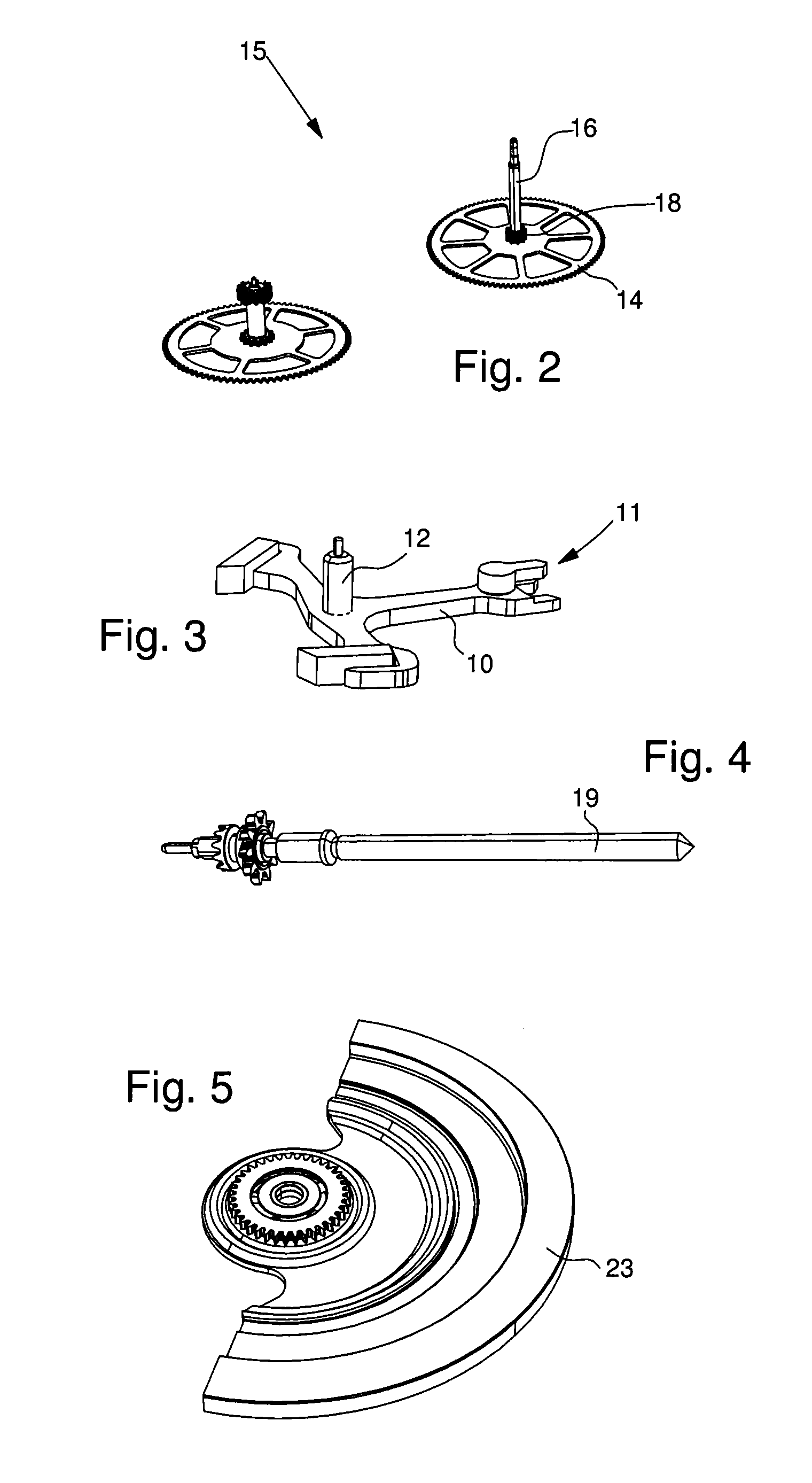
[0043]FIG. 1 also shows that movement 1 preferably includes an escapement system 9 comprising a Swiss lever 11 and an escape wheel 13 intended to distribute to gear train 15 the motions of the resonator and also to maintain them. Escapement system 9 is preferably mounted between two bars 6, 8 and main plate 4.
[0044]Finally, gear train 19 is intended to transmit the energy from the barrel (not shown) to the resonator...
PUM
| Property | Measurement | Unit |
|---|---|---|
| Fraction | aaaaa | aaaaa |
| Fraction | aaaaa | aaaaa |
| Fraction | aaaaa | aaaaa |
Abstract
Description
Claims
Application Information