
Method and Device for Ionizing Particles of a Sample Gas Flow

a gas flow and ionizing particle technology, applied in the direction of particle separator tube details, separation processes, instruments, etc., can solve the problem of difficult measurement of trace amounts of gaseous compounds for example from air, and achieve the effect of removing the wall

Active Publication Date: 2016-05-05
UNIVERSITY OF HELSINKI
View PDF5 Cites 6 Cited by
  • Summary
  • Abstract
  • Description
  • Claims
  • Application Information

AI Technical Summary

Benefits of technology

The invention provides a method and device for detecting extremely low concentrations of gas phase constituents in a sample gas flow. It particularly eliminates the problem of "wall effects" that can induce undesired signals and interfere with measurements. This is achieved by heavily saturating the inner walls and structures of the ionizer with acids, which prevents base particles from interacting with the walls and forming salts that are non-vaporizable and cannot interfere with the measurements. These technical effects offer significant advantages over the known prior art solutions and ensure accurate and reliable measurements.

Problems solved by technology

However, measurement of trace amounts of gaseous compounds for example from air is extremely difficult, as their concentration is minimal compared to the total air molecule concentration, and due to the large variety of the different gases compounds and their isotopes.
There are, however, some drawback related to known solutions namely particles to be determined may stick to inner wall structures of the ionizer and afterwards be released back to the sample gas flow and induce signal in a detector.
Anyway this is a very undesired feature because the particles are released very randomly and thus they will disturb the measurement at first by sticking into the structure and thereby reducing a signal to be measured, and secondly by releasing to the later sample flow and increasing the signal of the later sample flow to be detected.

Method used


Image

  • Method and Device for Ionizing Particles of a Sample Gas Flow
  • Method and Device for Ionizing Particles of a Sample Gas Flow

Examples


Embodiment Construction

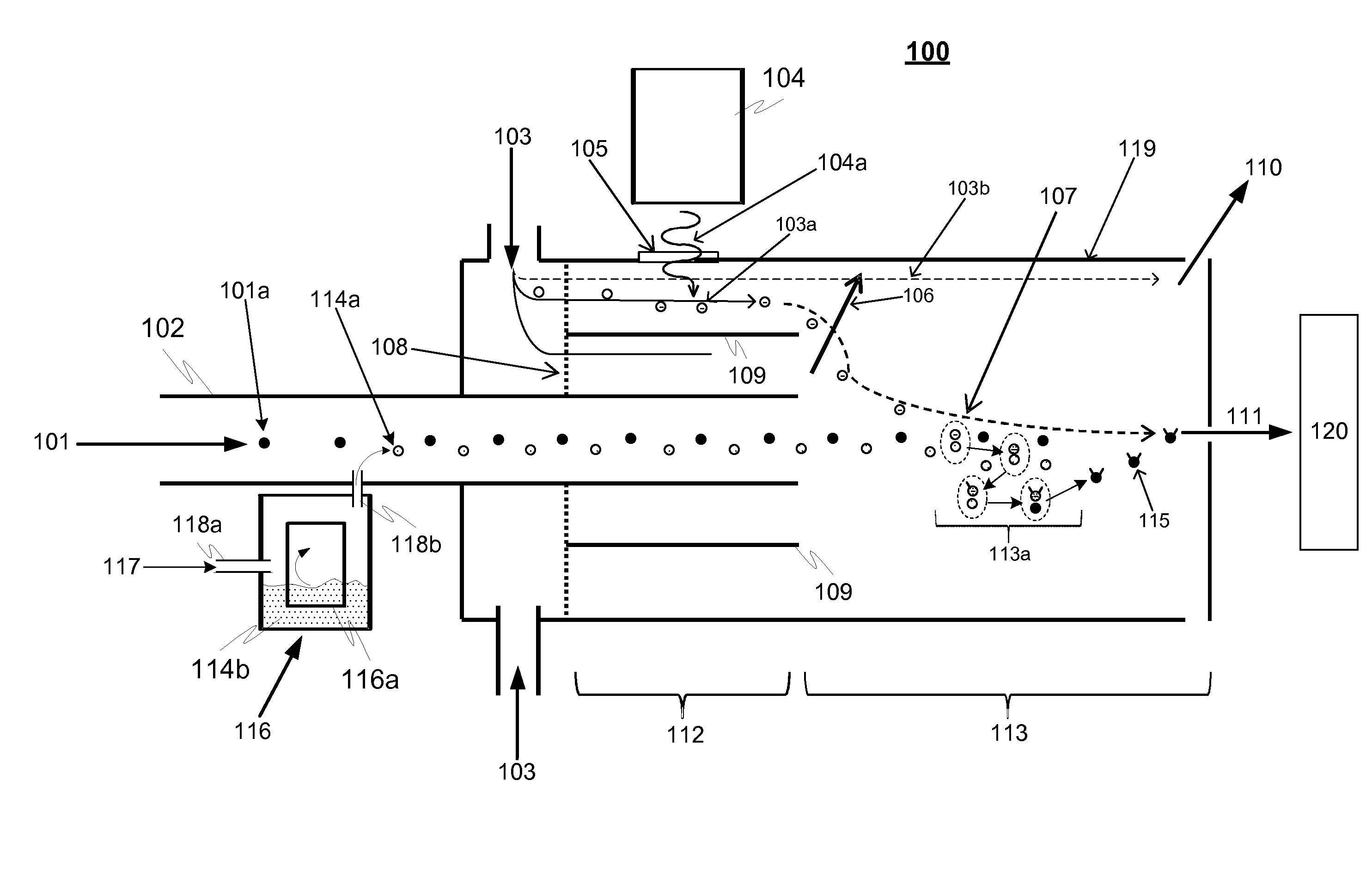
[0021]FIG. 1 is a principle-level schematic illustration of both a method and a device 100 for ionizing particles of a sample gas flow according to an advantageous embodiment of the invention. The device 100 comprises an inlet, which can be in the form of a first flow tube 102 for providing the sample gas flow 101. In addition the device comprises a generator 104 for producing reagent primary ions 103a from particles of candidate reagent gas flow 103 essentially in a primary ion production region 112 (region where the ionizing radiation ionizes the candidate reagent gas flow 103). The generator 104 may be an X-ray radiation or α-radiation source or a corona discharge source, as an example. These are only examples and also other types of sources can be used, such as β-radiation source.

[0022]In addition the device comprises also providing means 116 for providing and introducing H2SO4 molecules, preferably vapour, 114a to an interaction region 113. The H2SO4 providing means is advantag...


PUM


Abstract

A device for ionizing sample particles of a sample gas flow comprises a first flow tube for providing the sample gas flow, and an introducing means for providing H2SO4 molecules to an interaction region. In addition the device comprises a generator for producing reagent primary ions from particles of candidate reagent gas flow essentially in a primary ion production region. The device is configured to introduce said reagent primary ions with H2SO4 molecules in said interaction region in order to arrange interaction between the reagent primary ions and the H2SO4 molecules, thereby producing HSO4− ions and again to produce HSO4− ion clusters comprising HSO4− ions and at least two H2SO4 molecules via interactions of HSO4− with other H2SO4 molecules in said interaction region. Furthermore the device is configured to introduce said HSO4− ion clusters with the sample particles of the sample gas flow in order to provide reactions between said HSO4− ion clusters and the sample particles, and thereby provide a sample cluster comprising the HSO4− ion clusters and said base sample to be determined.

Description

TECHNICAL FIELD OF THE INVENTION[0001]The invention relates to a method and device for ionizing particles of a sample gas flow before a detector, such as a mass spectrometer, in order to determine properties, such as masses or concentrations, of gas phase samples or especially molecules or clusters, for example gas phase bases, such as ammonia and especially amines.BACKGROUND OF THE INVENTION[0002]An accurate mass spectrometry methods for determining of properties of gas phase samples are in very important role e.g. in atmospheric studies, such as studying e.g. roles of different chemical substances, such as ammonia, amines, in atmospheric nanoparticle formation. Especially there is a need for better knowing or determination of low concentrations and variability of atmospheric ammonia and amines and highly oxidized organics, as an example. In addition very accurate methods for determining of properties of gas phase samples, such as amines, are needed also in other fields, such as in...

Claims


Application Information

Patent Timeline
IPC IPC(8): H01J49/14H01J49/26H01J49/12G01N27/62
CPCH01J49/145H01J49/26H01J49/12G01N27/622H01J49/0077
Inventor SIPILA, MIKKOJUNNINEN, HEIKKIWORSNOP, DOUGLAS
Owner UNIVERSITY OF HELSINKI
Learn More