Cross-coupled oscillator, integrated circuit and electronic device

a cross-coupled oscillator and integrated circuit technology, applied in oscillator, pulse generator, pulse technique, etc., can solve problems such as cross-coupled oscillator design

Active Publication Date: 2016-05-05
MEDIATEK SINGAPORE PTE LTD SINGAPORE
View PDF5 Cites 1 Cited by
  • Summary
  • Abstract
  • Description
  • Claims
  • Application Information

AI Technical Summary

Benefits of technology

[0016]According to an optional feature of the invention, the cross-coupled oscillator has at least one capacitance arranged to minimise perturbations on the second potential and located across at least one of: the first

Problems solved by technology

This cross-coupled oscillator design suffers from the fact that a significant s

Method used


Image

  • Cross-coupled oscillator, integrated circuit and electronic device
  • Cross-coupled oscillator, integrated circuit and electronic device
  • Cross-coupled oscillator, integrated circuit and electronic device

Examples


Embodiment Construction

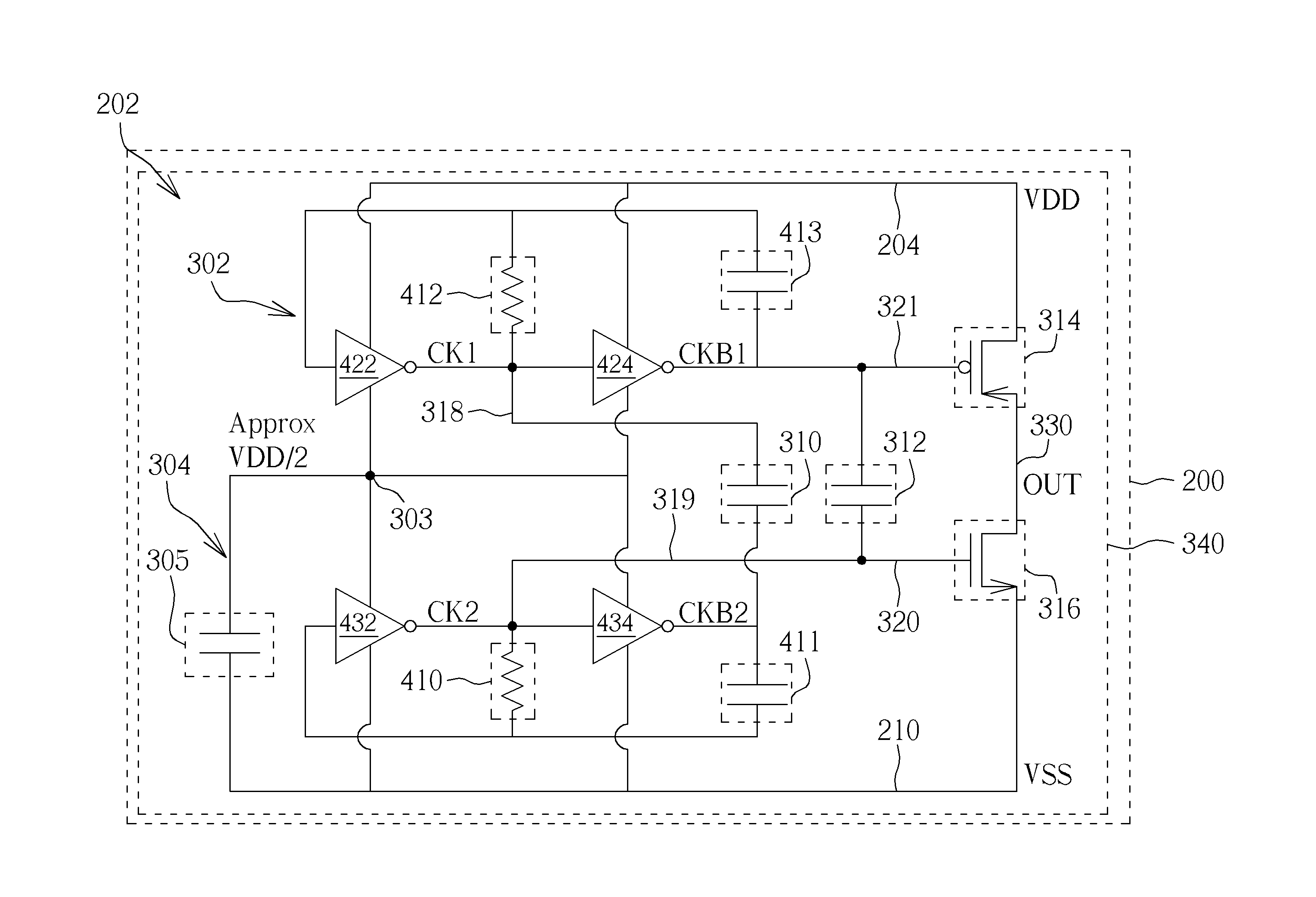
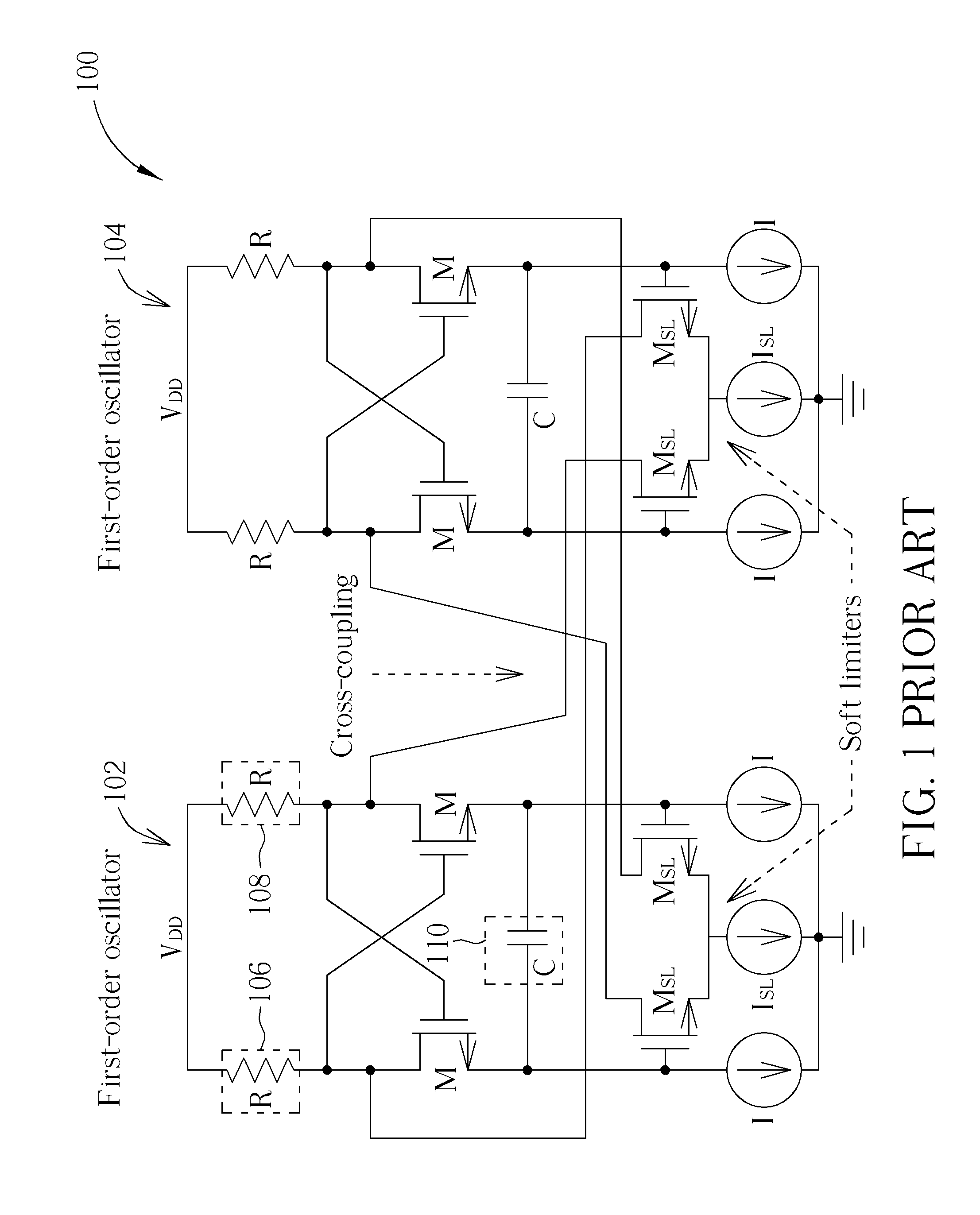
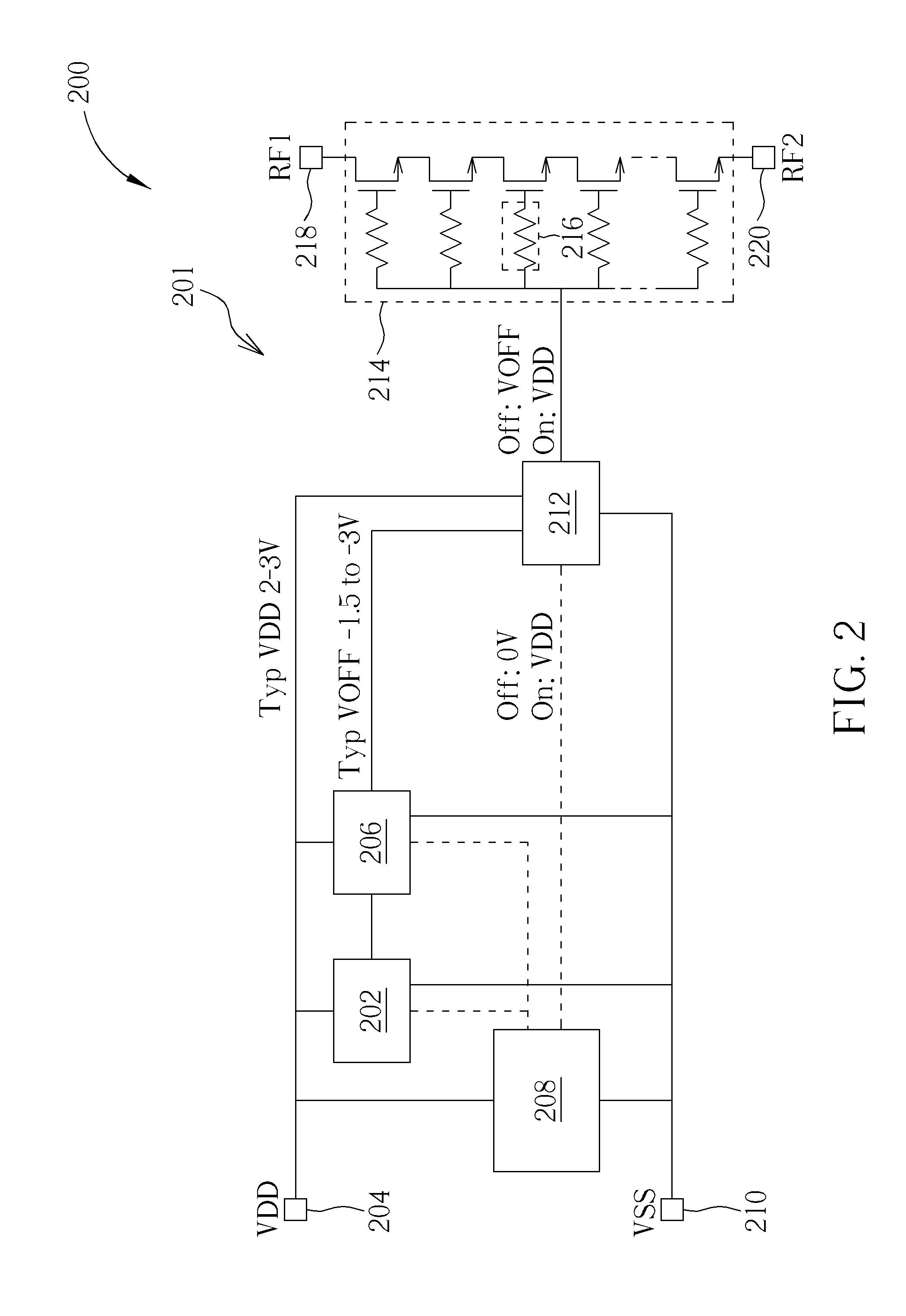
[0028]Examples of the invention will be described in terms of a cross-coupled oscillator circuit that is suitable for use with a charge pump to generate a negative bias for correctly turning off a high power RF switch. In examples of the invention, the cross-coupled oscillator circuit may be arranged to balance the duty cycle of the oscillator output by providing a complementary oscillator that employs two oscillator cores and cross-couples the output nodes of the oscillator cores, unlike the known cross-coupled oscillator architecture of FIG. 1 that uses current feedback between cores to generate quadrature signals. Examples of the invention will also be described in terms of a series-connected cross-coupled oscillator circuit, whereby the oscillator cores of the oscillator circuit share the same supply, but with different potentials, unlike known cross-coupled oscillator circuits that may share the same supply but also share the exact same potentials. In this manner, the oscillato...


PUM


Abstract

A cross-coupled oscillator arrangement has a first resistance-capacitance oscillator core including at least two inverting stages; and a second resistance-capacitance oscillator core substantially identical to the first resistance-capacitance oscillator core. The first oscillator core and second oscillator core are cross coupled in anti-phase using coupling capacitors. The first oscillator core and second oscillator core are also connected in series such that the first oscillator core is supplied with a supply between a first potential and a second potential and the second oscillator core is supplied with a supply between the second potential and a third potential.

Description

CROSS REFERENCE TO RELATED APPLICATIONS[0001]This application claims the benefit of U.S. provisional application No. 62 / 072,404, filed on Oct. 29, 2014 and incorporated herein by reference.BACKGROUND OF THE INVENTION[0002]1. Field of the Invention[0003]The field of this invention relates to a cross coupled oscillator, an integrated circuit comprising a cross coupled oscillator and an electronic device, for example comprising a charge pump and a high power radio frequency (RF) switch arranged to use a clock signal generated by the cross coupled oscillator.[0004]2. Description of the Prior Art[0005]In the field of radio frequency (RF) switches, such as RF silicon-on-insulator (SOI) switches, generally a negative bias is required in order to disable (turn ‘off’) the SOI switches under a large RF swing. The generation of a negative bias allows the RF switch designer to avoid the use of DC blocking capacitors. Such a negative bias is commonly generated by utilising a charge pump circuit,...

Claims


Application Information

Patent Timeline
IPC IPC(8): H03B5/12
CPCH03B5/1212H03B5/26H03K3/0231
Inventor TENBROEK, BERNARD MARK
Owner MEDIATEK SINGAPORE PTE LTD SINGAPORE
Why Eureka
Try Eureka