Dual-mode microwave resonator device and method of electron spin resonance measurement

a microwave resonator and electron spin technology, applied in the direction of measurement devices, magnetic measurements, instruments, etc., can solve the problems of not being able to detect all possible orientations, not being able to achieve the right approach of a low-q resonator at high frequencies, and not being able to achieve the right approach

Inactive Publication Date: 2016-03-15
MAX PLANCK GESELLSCHAFT ZUR FOERDERUNG DER WISSENSCHAFTEN EV
View PDF24 Cites 3 Cited by
  • Summary
  • Abstract
  • Description
  • Claims
  • Application Information

AI Technical Summary

Benefits of technology

[0025]As a further advantage of the invention, there are no particular restrictions with regard to the shape of the resonator of the inventive microwave resonator device. As preferred examples, the resonator may have a rectangular cross-sectional shape or a cylindrical shape. In particular, for the electron spin resonance measurement application, the cylindrical shape of the resonator is preferred. As an advantage of the cylindrical resonator, the maximum field strength of both of the first and second microwave field modes is located at the same position in the first resonator section, so that the sample can be kept at this position during the measurement. With other applications, e.g. for filtering microwaves, the rectangular resonator shape can be used as well. The cylindrical configuration is, however, preferred. With the filtering applications, the inventive microwave resonator device provides a filter, which is adjustable in a broad frequency range.
[0026]According to a preferred embodiment of the invention, the conducting plate of the coupling section is arranged at a half longitudinal length of the resonator. In this case, the conducting plate is arranged at the field minimum of the second (higher harmonic) microwave field mode. If another higher harmonic frequency mode is used (for example TE013, TE014, etc.) as the second microwave field mode, another position along the longitudinal axis of the resonator can be selected. Furthermore, the conducting plate is preferably arranged perpendicularly to the longitudinal axis of the resonator. With the perpendicular arrangement, a perturbation of the second microwave field mode can be minimized.
[0027]According to further preferred embodiments of the invention, the conducting plate has a diameter of at least 2.2 mm, in particular at least 3.2 mm, and / or a thickness below 200 μm, in particular below 100 μm. The inventors have found that these parameters result in particular advantages for adjusting the first and second microwave mode frequencies for electron spin resonance measurements.

Problems solved by technology

As a consequence, the “pump” frequency is placed on the side of the resonator dip, where the pumping efficiency is not as good as at the centre of the dip.
This is not sufficient to detect all possible orientations for radicals in a pair.
With a single mode resonator, particularly at frequencies above 90 GHz, this is impossible.
This demonstrated that the approach of a low-Q resonator is not the right concept at high frequencies.
Another problem encountered is the usual need for low temperature measurements.
This complicates the design of any resonator.
However, these resonators are not capable of a simultaneous excitation of a sample at different microwave frequencies.

Method used


Image

  • Dual-mode microwave resonator device and method of electron spin resonance measurement
  • Dual-mode microwave resonator device and method of electron spin resonance measurement
  • Dual-mode microwave resonator device and method of electron spin resonance measurement

Examples


Embodiment Construction

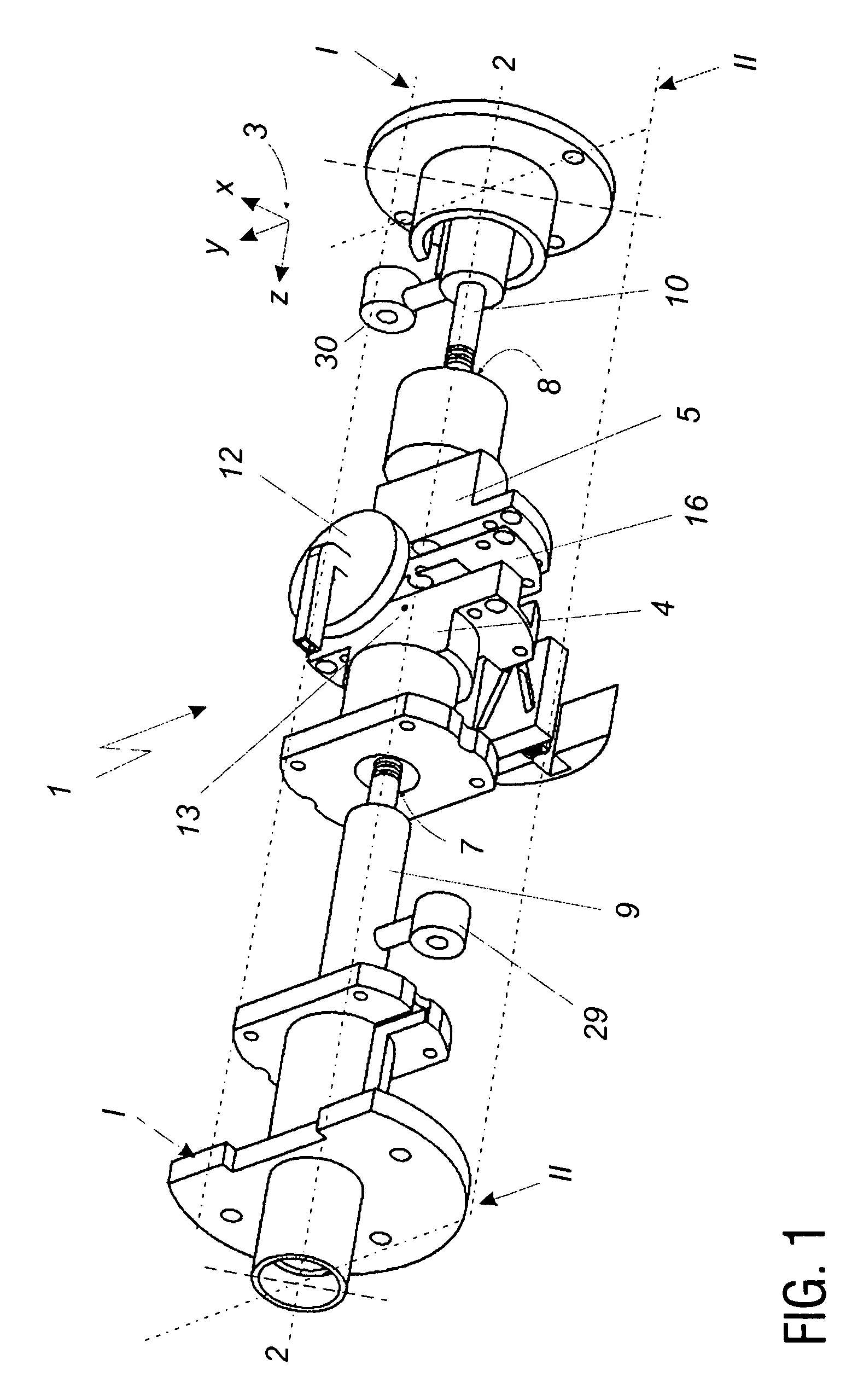
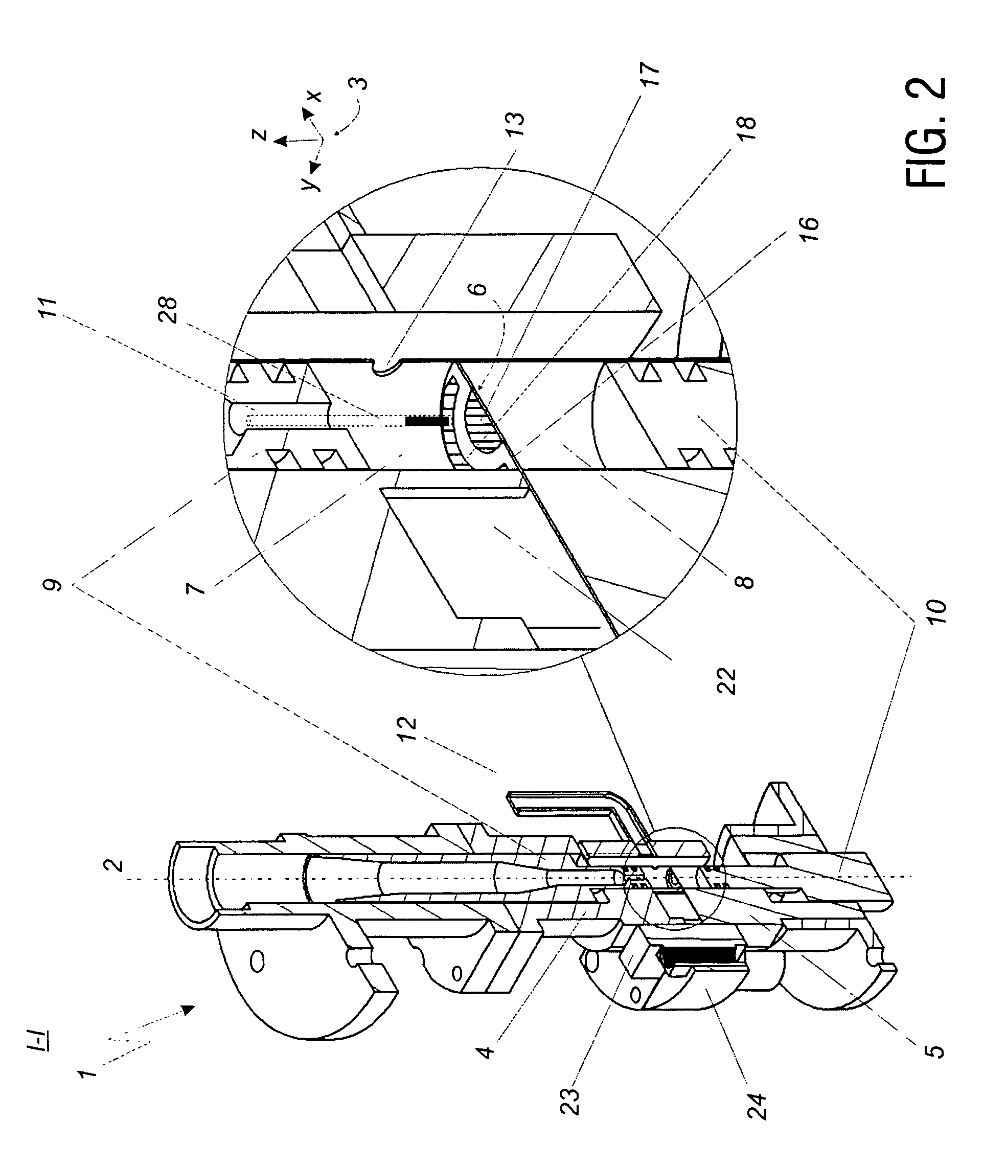
[0038]The general design of the dual-mode microwave resonator device is presented in the FIG. 1. The cross sections I-I and II-II of the assembled resonator with details of a junction between the resonance sections are sketched in FIG. 2 and FIG. 3, respectively. For ESR measurements, the dual-mode microwave resonator device is combined with further components of an ESR device (ESR spectrometer), like a magnet device providing a static magnetic field and a microwave source / detection system to induce and detect ESR signals. These components of the ESR device are not described in detail as they are designed as conventionally known from ESR technique.

[0039]The preferred embodiment of the microwave resonator device is referenced by numeral 1. The resonator extends along the longitudinal axis 2 which coincides with the z axis of the Cartesian coordinate system indicated by 3. The basic architecture of the resonator can be described as two cylindrical hollow resonance sections 7 and 8 pro...


PUM


Abstract

A microwave resonator device (1), being configured in particular for electron spin resonance measurements, comprises a resonator being resonant with first and second microwave field modes and including first and second resonance sections (7, 8) arranged along a longitudinal axis (2) of the resonator, and a coupling unit being arranged between the first and second resonance sections, wherein the coupling unit includes a conducting plate (16) being arranged on the longitudinal axis (2) and covering a central portion of a cross-sectional area of the resonator, the conducting plate (16) is adapted to adjust a first mode frequency of the first microwave field mode, and the conducting plate (16) is arranged at a field minimum of the second microwave field mode. Furthermore, a method of conducting an electron spin resonance measurement with a sample to be investigated is described.

Description

SUBJECT OF THE INVENTION[0001]The present invention relates to a microwave resonator device including a dual-mode microwave resonator, in particular for double electron spin resonance spectroscopy or for microwave filtering. More specifically, the invention relates to a dual-mode microwave resonator device configured for double electron-electron spin echo experiments (PELDOR, also called DEER) performed at W-band microwave frequencies (at and near 94 GHz). Furthermore, the present invention relates to a method of measuring electron spin resonances using the dual-mode microwave resonator device, in particular a method of double electron spin resonance spectroscopy. The invention can be applied in particular in the field of electron spin resonance (ESR, also EPR: electron paramagnetic resonance) spectroscopy.TECHNICAL BACKGROUND[0002]Atoms and molecules with unpaired electrons possess a magnetic moment generated by the electron-spin angular momentum. The magnetic moment can be detecte...

Claims


Application Information

Patent Timeline
Patent Type & Authority Patents(United States)
IPC IPC(8): G01R33/345G01R33/60H01P7/00
CPCH01P7/00G01R33/345G01R33/60
Inventor TKACH, IGORBENNATI, MARINA
Owner MAX PLANCK GESELLSCHAFT ZUR FOERDERUNG DER WISSENSCHAFTEN EV
Why Eureka
Try Eureka