Vibrating element, electronic device, electronic apparatus, and moving object

a technology of electronic devices and vibrating elements, applied in piezoelectric/electrostrictive/magnetostrictive devices, oscillator generators, semiconductor devices, etc., can solve the problems of reduced yield of vibrating elements, increased manufacturing costs of vibrating elements, and difficulty in completely eliminating them, so as to reduce cost and cost

Active Publication Date: 2016-05-05
SEIKO EPSON CORP
View PDF2 Cites 10 Cited by
  • Summary
  • Abstract
  • Description
  • Claims
  • Application Information

AI Technical Summary

Benefits of technology

[0031]According to these application examples, since the moving object includes the vibrating element satisfying a desired CI specif

Problems solved by technology

However, even with the use of the manufacturing method of the flexural vibrator element disclosed in JP-A-2013-9221, it is difficult to completely eliminate the oblique vibration of the vibrating element, so that there is a problem that the manufacturing cost of the vibrating element is increased due t

Method used


Image

  • Vibrating element, electronic device, electronic apparatus, and moving object
  • Vibrating element, electronic device, electronic apparatus, and moving object
  • Vibrating element, electronic device, electronic apparatus, and moving object

Examples


embodiment 1

Vibrating Element

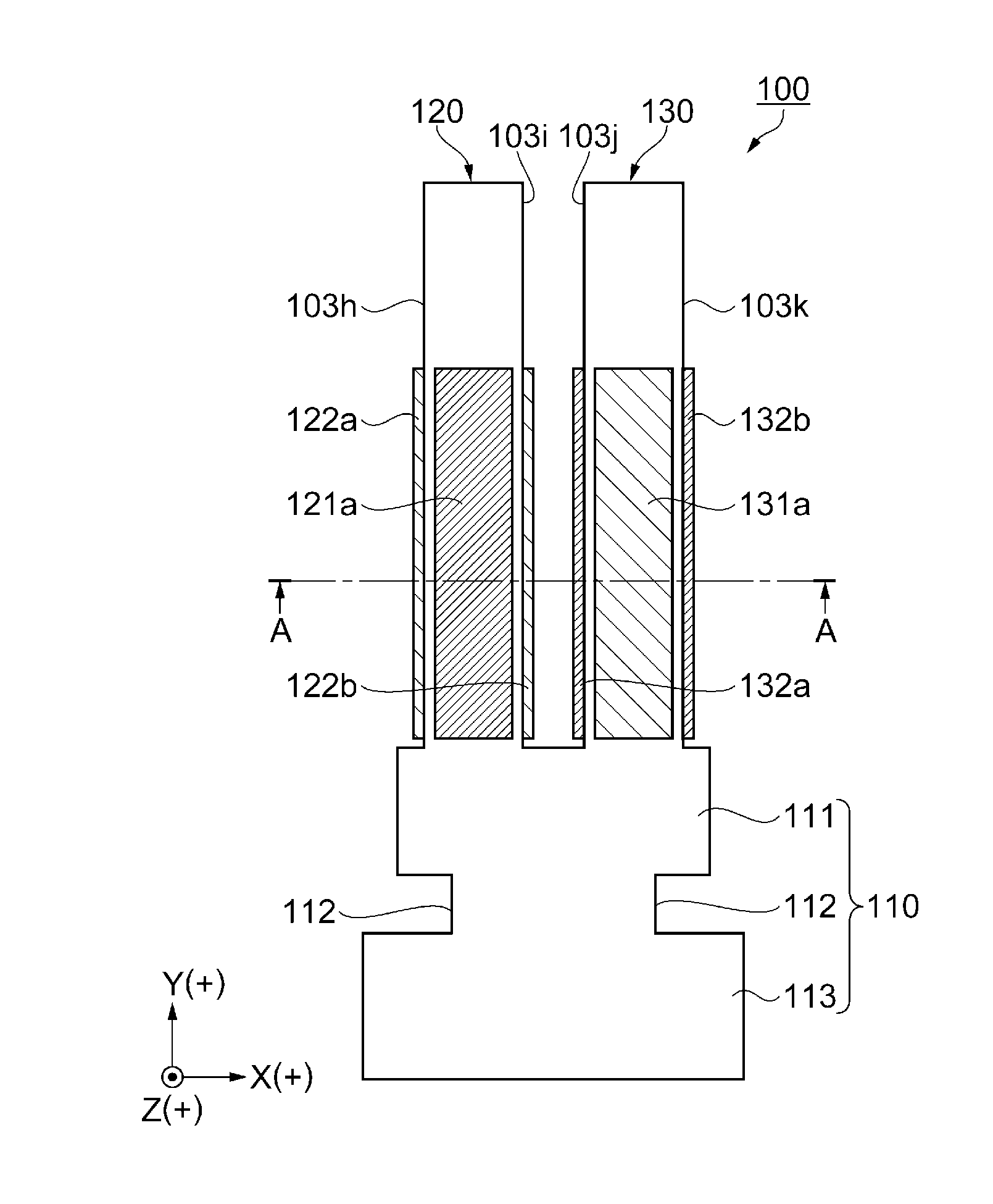
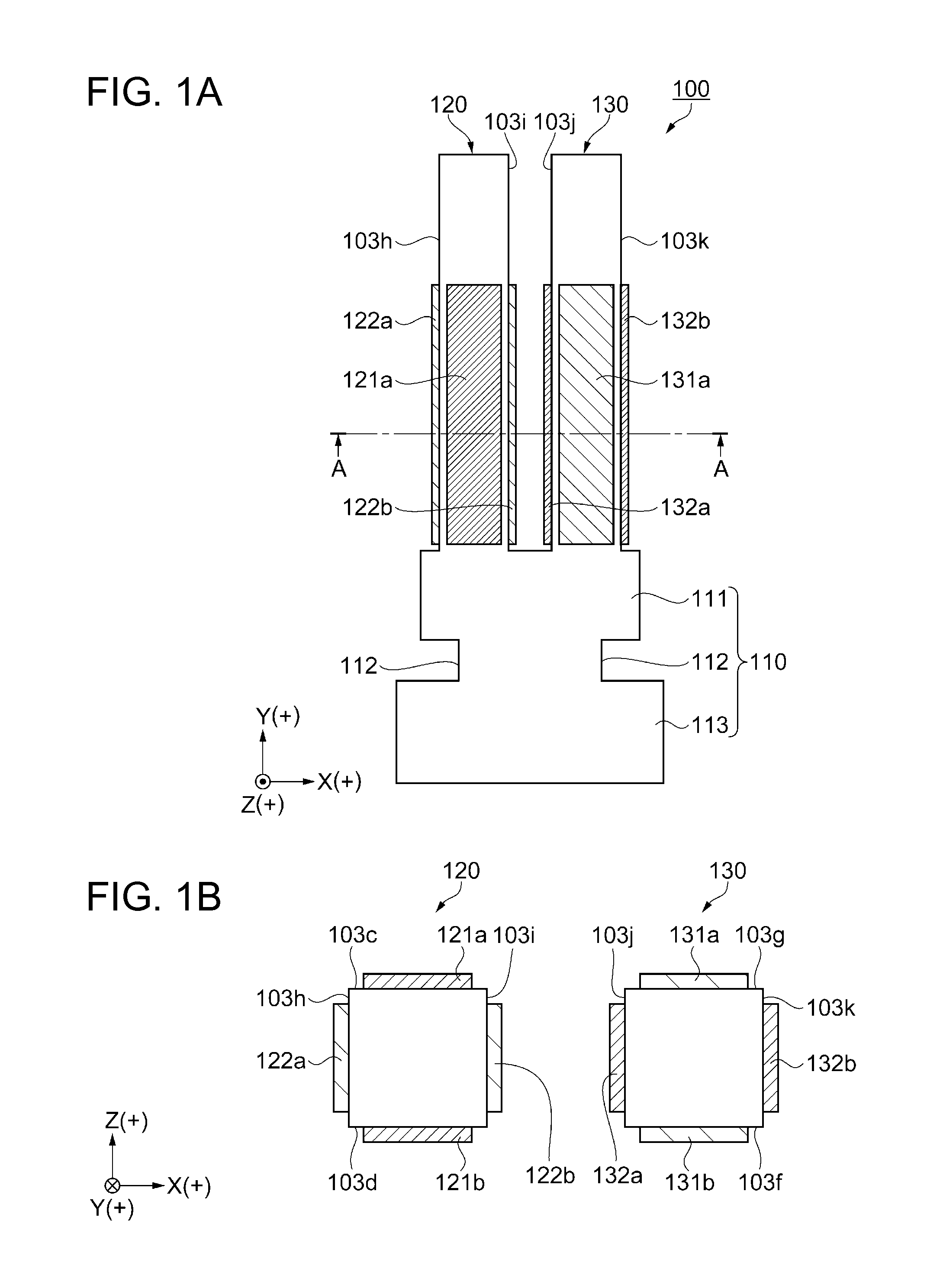
[0047]First, a schematic configuration of a vibrating element according to Embodiment 1 will be described with reference to FIGS. 1A and 1B. FIG. 1A is a plan view schematically showing a schematic configuration of a tuning fork-type vibrator element as a vibrating element according to Embodiment 1. FIG. 1B is a cross-sectional view taken along the line A-A in FIG. 1A.

[0048]As shown in FIGS. 1A and 1B, the tuning fork-type vibrator element 100 as a vibrating element includes drive vibrating arms 120 and 130 as vibrating arms that perform a flexural vibration, and later-described drive electrodes provided on the drive vibrating arms 120 and 130. The tuning fork-type vibrator element 100 includes a base portion 110. The drive vibrating arms 120 and 130 extend in pairs in the +Y-axis direction from one of edges of the base portion 110 in the Y-axis direction. The base portion 110 has a plate shape including a narrow width portion 111 and a wide width portion 113 dispos...

embodiment 2

Gyro Element-1

[0069]First, a gyro element as a vibrating element according to Embodiment 2 will be described with reference to FIGS. 5A to 6B. FIG. 5A is a perspective view schematically showing the gyro element; and FIG. 5B is a plan view schematically showing the gyro element. FIGS. 6A and 6B are diagrams for explaining an electrode configuration of the gyro element, in which FIG. 6A is a cross-sectional view taken along the line C-C in FIG. 5B and FIG. 6B is a cross-sectional view taken along the line D-D in FIG. 5B.

[0070]As shown in FIG. 5A, the gyro element 300 according to Embodiment 2 includes a base portion 1, drive vibrating arms 2a and 2b as vibrating arms, detection vibrating arms 3a and 3b as detection arms, and adjusting vibrating arms 4a and 4b, all of which are integrally formed by processing a base material (material constituting a main portion). Further, the gyro element 300 is provided with a first coupling portion 5a extending from the base portion 1, a first supp...

embodiment 3

Gyro Element-2

[0099]Next, a gyro element 400 as a vibrating element according to Embodiment 3 will be described with reference to FIG. 8.

[0100]FIG. 8 schematically shows a schematic configuration of the gyro element according to Embodiment 3, and is a plan view of the gyro element as viewed from the +side of the Z-axis direction. The gyro element 400 is provided with a detection signal electrode, a detection signal wiring, a detection signal terminal, a detection ground electrode, a detection ground wiring, a detection ground terminal, a drive signal electrode, a drive signal wiring, a drive signal terminal, a drive ground electrode, a drive ground wiring, a drive ground terminal, and the like, all of which are omitted in FIG. 8.

[0101]The gyro element 400 according to Embodiment 3 is an “out-of-plane axis detection-type” sensor element that detects an angular velocity about the Z-axis. Although not shown in the drawing, the gyro element 400 includes a base material, and pluralities ...


PUM


Abstract

A tuning fork-type vibrator element as a vibrating element includes a drive vibrating arm that performs a flexural vibration, and a drive electrode (a first drive electrode and a second drive electrode) provided on the drive vibrating arm. When a direction in which the drive vibrating arm extends is a Y-axis, a direction in which the drive vibrating arm performs a primary vibration is an X-axis, and a direction orthogonal to the Y-axis and the X-axis is a Z-axis, the drive vibrating arm performs the flexural vibration with a displacement ratio of greater than 0% and 20% or less where the displacement ratio is obtained by dividing a displacement amount in the Z-axis direction by a displacement amount in the X-axis direction.

Description

BACKGROUND[0001]1. Technical Field[0002]The present invention relates to a vibrating element, an electronic device, an electronic apparatus, and a moving object.[0003]2. Related Art[0004]In the related art, a vibrating element in which, for example, a vibrating arm is caused to perform a flexural vibration utilizing a piezoelectric phenomenon of a piezoelectric body such as quartz crystal is known. The vibrating element using quartz crystal has excellent frequency-temperature characteristics, and therefore is widely used as a reference frequency source or a signal transmission source in various types of communication apparatuses or electronic apparatuses. Moreover, a gyro sensor is used in electronic apparatuses that perform car body control in a vehicle, self-position detection of a car navigation system, vibration control correction (so-called camera shake correction) of a digital camera, a camcorder, and a mobile phone, and the like. The vibrating element that perform the flexura...

Claims


Application Information

Patent Timeline
IPC IPC(8): H03H9/21H03B5/30
CPCH03B5/30H03H9/21H01L2224/48091H01L2224/48227H01L2224/73265H03H9/02062H01L2924/00014
Inventor NAKAGAWA, KEIJI
Owner SEIKO EPSON CORP
Why Eureka
Try Eureka