Correction in slit-scanning phase contrast imaging

a phase contrast and correction technology, applied in imaging devices, instruments, applications, etc., can solve the problems of tight requirements on the accuracy of stepping devices, and the fringe profile achieved may not look like the ideal fringe pattern, and achieve the effect of interfering capability of x-rays

Inactive Publication Date: 2016-05-12
KONINKLJIJKE PHILIPS NV
View PDF1 Cites 6 Cited by
  • Summary
  • Abstract
  • Description
  • Claims
  • Application Information

AI Technical Summary

Benefits of technology

[0006]This allows removing the gain induced disturbance of the Moiré fringe distribution by referencing the pixel output to a flat field referencing image. The flat field reference image in a differential phase contrast imaging setup provides the removal of the Moiré fringes without having to detune the interferometer setup. In particular, the calibration filter grating according to the present invention avoids the detuning of the interferometer setup and in particular the removal of significant parts. The calibration filter grating provides a removal of the coherent part of the X-ray radiation provided by the primary grating (grating G0) before the X-ray flux is passing the interferometer gratings in form of the phase grating (grating G1) and the analyzer grating (grating G2). The coherent part is transformed by the filter into incoherent X-rays before the X-rays enter the interferometer, or in case of an arrangement of the filter between G1 and G2—before the X-rays enter the analyzer grating of the interferometer. As an effect, the filter material with the structural elements comprises structural parameters in the micrometer region, random small angle scattering is provided. Therefore, the filter material has dark field property, which causes the de-coherence of the X-rays passing the material. The arrangement of the calibration filter as a coarse grating provides the advantage that the filter can remain arranged in an imaging system, i.e. in the path of the X-ray beam, since the bars of the filter are movable to be aligned either with the bars of the device, e.g. a pre-collimator, splitting the X-ray beam into a number of X-ray strips, for slit-scanning imaging, or aligned with openings of the device splitting X-ray beam, for calibrating.
[0023]As an advantage, an X-ray phase contrast imaging arrangement is provided that can be calibrated in particular with respect to identifying and removing disturbance in the Moiré pattern due to individual gain factors. The imaging arrangement can advantageously be provided in a compact manner. Since the calibration filter grating needs to be moved only in the amount of half the pitch of the filter grating structure, the filter grating can be provided in an integrated manner leading to a facilitated design with increased compatibility with respect to other equipment in an examination room.
[0035]According to an example, the calibration filter grating is arranged with a calibration distance of approximately 5 to 10 mm from the phase grating. In an example, the calibration filter grating is arranged half distance between the X-ray source grating G0 and the phase grating G1. The “filter” strength may then be reduced to approximately half the amount, but this may be compensated by the double filter thickness, but also intrinsic absorption is enhanced.
[0040]As an advantage, an imaging system is provided that can be calibrated in a routine manner and also on demand. This results in an increased image quality due to improved image data and thus supports the analytical and diagnostic procedures performed by a doctor or other clinical staff.
[0056]According to the invention, the Moiré fringe pattern resulting from the coherent X-ray radiation is temporarily suppressed by temporarily inserting a special filter grating into the X-ray path that cancels the coherence and thus the interference capability of the X-rays. The provision of a filter grating provides the effect that the filter does not need to be removed out of the radiation beam, but only needs to be moved laterally such that the bars of the filter grating are aligned with the slit arrangement of the pre-collimator, i.e. the filter grating bars are aligned with the slits of the pre-collimator for calibration scanning and for slit-scanning, the filter grating bars are aligned with the bars of the pre-collimator. In an example, lightweight material with internal microstructures is provided, wherein the dimensions of the microstructures may be close to the pitch of the interferometer grating. Thus, a flat field reference image can be acquired, which can then be used for calibration purposes. The movement and thus insertion of the de-coherence flat field filter grating into the parts of the X-ay beam that hit the detector portions may be done manually by hand or motor-driven, and computer-controlled by a translation stage. The special filter grating can be arranged in between the source grating and the G2 grating of the interferometer unit. Its preferable position with respect to available space and efficiency is just in front of the interferometer unit, or also just in front of the pre-collimator.

Problems solved by technology

Since these gratings have pitches in the order of a few micrometers only, there are tight requirements on the accuracy of the stepping device that performs the relative movement of the gratings.
However, the fringe profile achieved may not look like the ideal fringe pattern.

Method used


Image

  • Correction in slit-scanning phase contrast imaging
  • Correction in slit-scanning phase contrast imaging
  • Correction in slit-scanning phase contrast imaging

Examples


Embodiment Construction

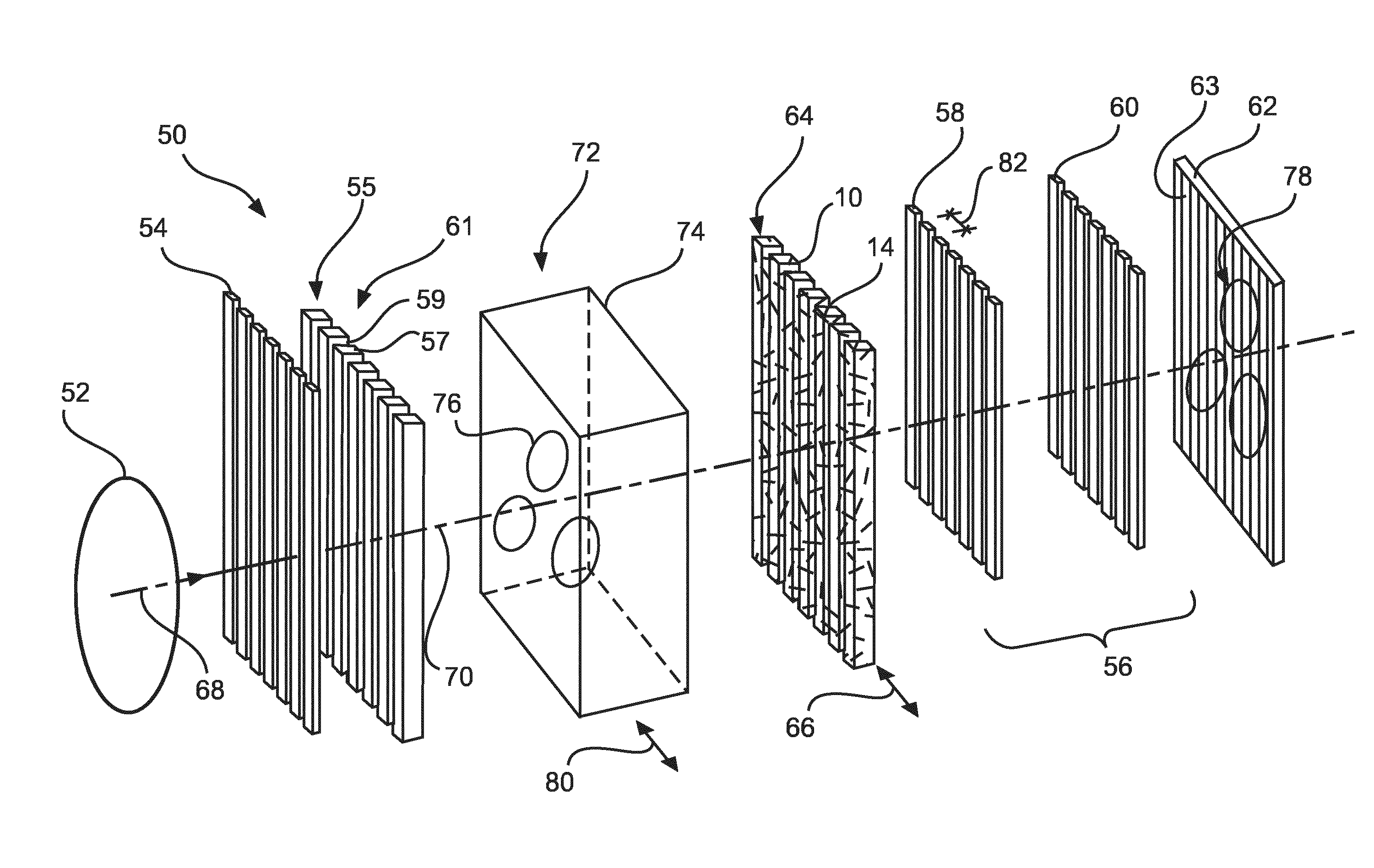
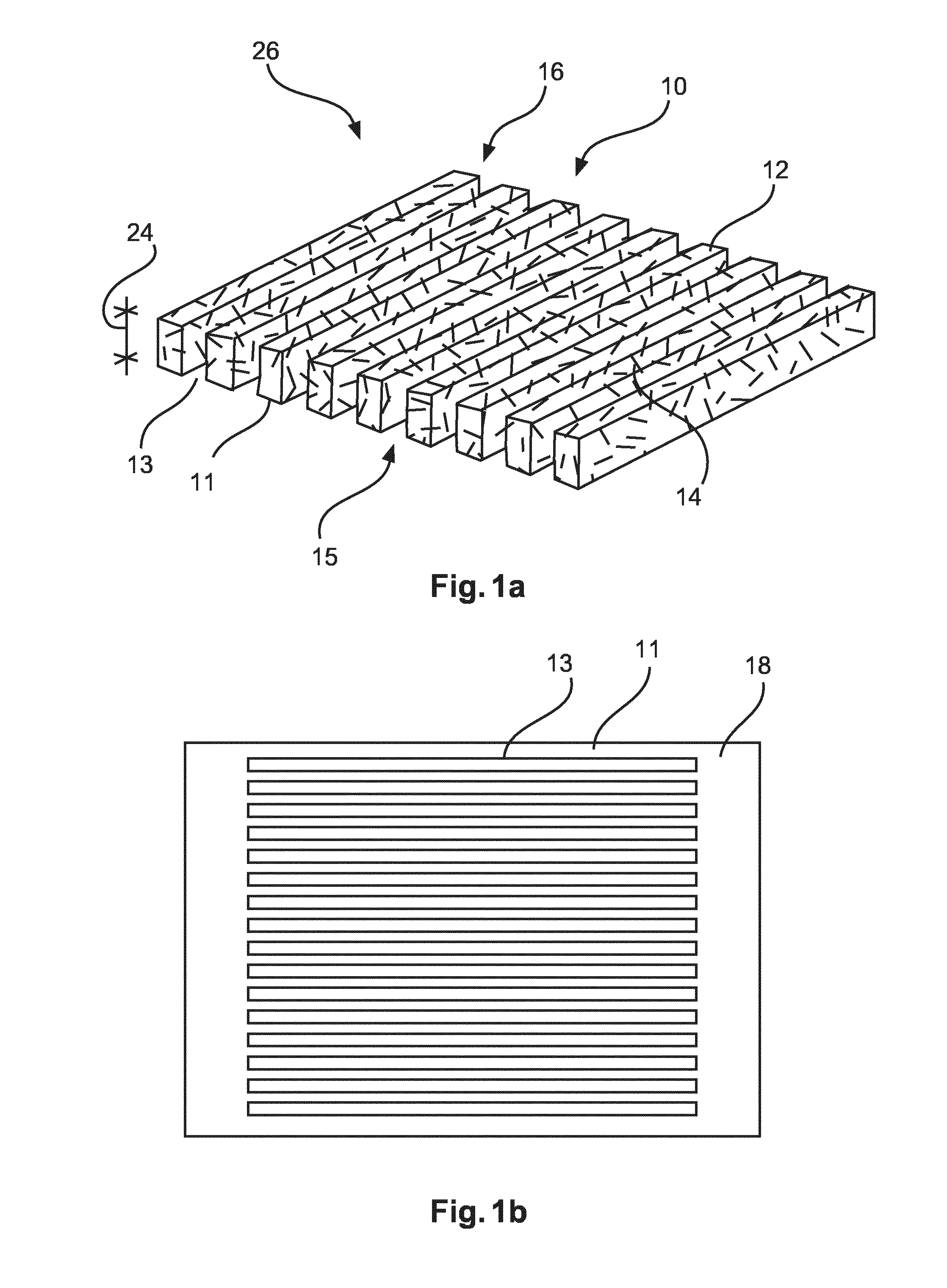
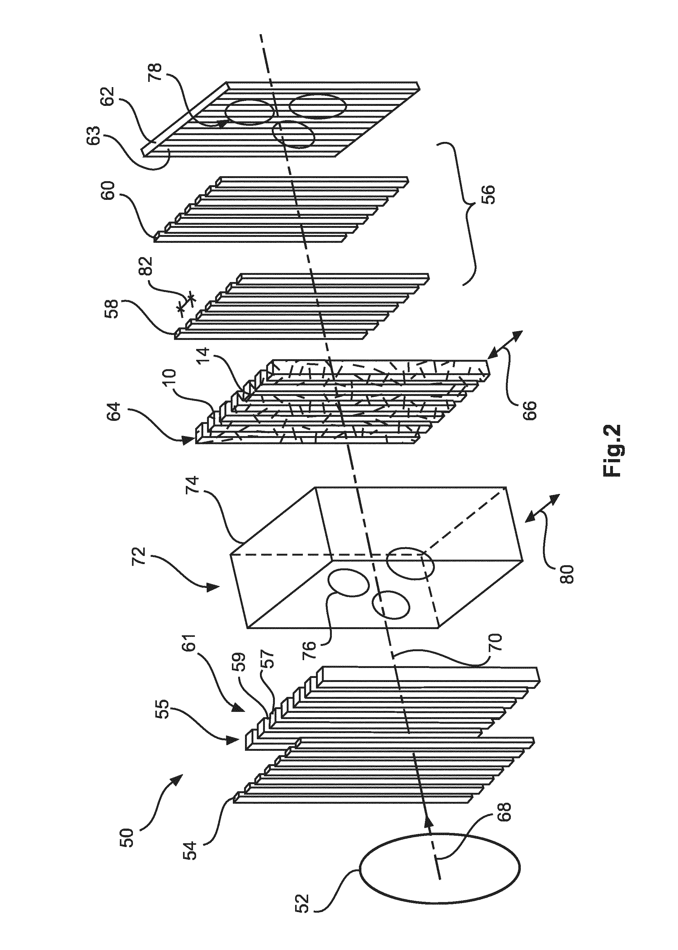
[0069]FIG. 1A shows a calibration filter grating 10 for an X-ray phase contrast imaging arrangement. The calibration filter grating 10 comprises a first plurality of filter segments 11 comprising a filter material 12. The filter material 12 is made from a material with structural elements 14, which are only schematically indicated in FIG. 1A without being to scale, comprising structural parameters in the micrometer region. Further, second plurality of opening segments 13 is provided. The filter segments 11 and the opening segments 13 are arranged alternating as a filter pattern 15. The calibration filter grating 10 is configured to be movably arranged between an X-ray source grating and an analyzing grating of an interferometer unit in a slit-scanning system of a phase contrast imaging arrangement, which will also be explained in more detail in relation with FIGS. 2 to 6. The filter pattern 15 is configured to be aligned with a slit pattern of the slit-scanning system (see also belo...


PUM

PropertyMeasurementUnit
sizeaaaaaaaaaa
sizeaaaaaaaaaa
sizeaaaaaaaaaa

Abstract

The present invention relates to calibration in X-ray phase contrast imaging. In order to remove the disturbance due to individual gain factors, a calibration filter grating (10) for a slit-scanning X-ray phase contrast imaging arrangement is provided that comprises a first plurality of filter segments (11) comprising a filter material (12) and a second plurality of opening segments (13). The filter segments and the opening segments are arranged alternating as a filter pattern (15). The filter material is made from a material with structural elements (14) comprising structural parameters in the micrometer region. The filter grating is movably arranged between an X-ray source grating (54) and an analyzer grating (60) of an interferometer unit in a slit-scanning system of a phase contrast imaging arrangement. The slit-scanning system is provided with a pre-collimator (55) comprising a plurality of bars (57) and slits (59). The filter pattern is aligned with the pre-collimator pattern (61).

Description

FIELD OF THE INVENTION[0001]The present invention relates to calibration in slit-scanning X-ray phase contrast imaging, and relates in particular to a calibration filter grating for a slit-scanning X-ray phase contrast imaging arrangement, to a slit-scanning X-ray phase contrast imaging arrangement, to an X-ray imaging system, and to a method for calibration in slit-scanning X-ray phase contrast imaging, as well as to a computer program element and a computer-readable medium.BACKGROUND OF THE INVENTION[0002]For phase contrast imaging based on slit-scanning, for example for differential phase contrast imaging (DPCI), a required pre-processing step is flat field correction in the imaging applications. DPCI is an emerging technology that has the potential to improve the diagnostic value of X-ray imaging. A DPCI system may be provided with three gratings used between the X-ray source and the detector. The acquisitions of several X-ray images at different relative positions of two of the...

Claims


Application Information

Patent Timeline
Patent Type & Authority Applications(United States)
IPC IPC(8): A61B6/00G01N23/20G21K1/10
CPCA61B6/582A61B6/484G01N23/20075G21K1/10G02B5/1838G21K1/06G01N2223/303A61B6/5258A61B6/583G21K2207/005
Inventor ROESSL, EWALDMARTENS, GERHARD
Owner KONINKLJIJKE PHILIPS NV
Why Eureka
Try Eureka