System and method for estimating rig state using computer vision for time and motion studies

a computer vision and rig state technology, applied in the field of system and method for estimating rig state using computer vision for time and motion studies, can solve the problems of difficult to measure the significant portion of rig activities and sensing problems, and the individual sensors do not have direct access to the big-picture rig state, so as to improve the automatic decision-making and rig control

Active Publication Date: 2016-05-12
HELMERICH & PAYNE TECH LLC
View PDF3 Cites 12 Cited by
  • Summary
  • Abstract
  • Description
  • Claims
  • Application Information

AI Technical Summary

Benefits of technology

[0005]By applying automated, computer-based video interpretation, continuous, robust, and accurate assessment of many different phenomena can be achieved through pre-existing video data without requiring a person-in-the-loop. Automated interpretation of video data is known as computer vision, and recent advances in computer vision technologies have led to significantly improved performance across a wide range of video-based sensing tasks. Computer vision can be used to improve safety, reduce costs and improve efficiency.
[0009]Significant effort is often spent analyzing hours and days of video feeds from rigs to perform time & motion studies (“T&M studies”), which are typically focused on one or two classical “drilling states”—e.g., improving time spent pulling out of hole. Since raw video data is not annotated, it is extremely difficult to “jump” to the next instance of any particular state without having watched and annotated the whole video first; which is very time consuming and error-prone. It is also currently not possible to automatically determine, from the observed video and down-well data, the amount of time spent in any one state. However, these important T&M parameters could be automatically estimated if state data could be automatically inferred and added to the video data stream. Incorporation of this information could make all other rig automation and sensing technologies operate more smoothly and produce overall higher quality results.
[0010]Therefore there is a need for an automated computer vision based technique for observing and estimating large-scale information about the complete rig state. This will enable improved low-level processing by incorporating rig state into decision making, and enable improved T&M analyses and processing by providing automatically annotated video feeds for rig understanding.
[0012]Finally, automated rig state detection also enables improved automated decision making and rig control.

Problems solved by technology

Despite the multitude of sensors on today's rigs, a significant portion of rig activities and sensing problems remain difficult to measure with classical instrumentation, and person-in-the-loop sensing is often utilized in place of automated sensing.
Due to the complexity of modern drilling and the number of possible interacting human behaviors on a rig, aggregating data from each of these individual sensors is a very complicated task.
Importantly, none of the individual sensors has direct access to the big-picture rig state.
In other words, the large-scale activities occurring on the rig (e.g., adding barite to the pits, tripping, drilling ahead) are not readily deducible from each sensors readings in isolation, nor in aggregate.
Since raw video data is not annotated, it is extremely difficult to “jump” to the next instance of any particular state without having watched and annotated the whole video first; which is very time consuming and error-prone.
It is also currently not possible to automatically determine, from the observed video and down-well data, the amount of time spent in any one state.

Method used


Image

  • System and method for estimating rig state using computer vision for time and motion studies
  • System and method for estimating rig state using computer vision for time and motion studies
  • System and method for estimating rig state using computer vision for time and motion studies

Examples


Embodiment Construction

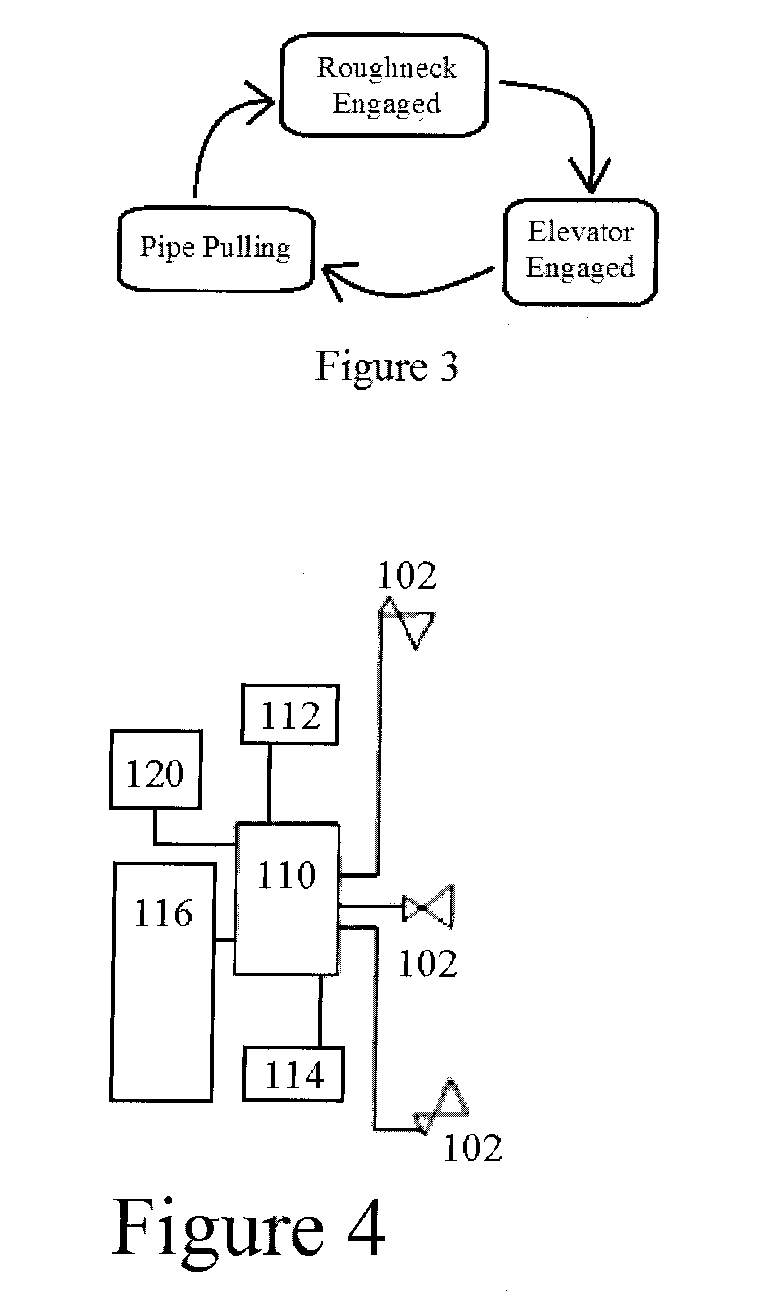
[0018]The Rig State Estimation system, (“RSE”), may contain several parts including a model of rig state not as a single discrete “state” that can be entered and exited from, but as a collection of facts about a rig that may be estimated and updated in real-time. In addition to multiple sensors 120, which may provide information such as measured surface readings or down-well measurements, RSE uses computer vision and machine learning algorithms specifically designed to estimate the rig state from video cameras 102. The resulting information about rig state may then be incorporated into a display, along with other relevant pieces of information (e.g., video frames) and the state information is used to improve algorithm performance by altering the relative importance of the variables under consideration and other algorithm-level modifications. The information may also be used to form T&M databases 112 and reports, and to annotate the collected video with relevant T&M information. This...


PUM


Abstract

The invention relates to a system and method for estimating global rig state. The system comprises a model incorporating multiple variables related to rig state, at least one camera operably connected to at least one processor wherein said camera is capable of gathering visual data regarding at least one variable of rig state and said processor is capable of compiling rig state data, estimating global rig state, or both. The system further comprises multiple sensors for measuring variables related to global rig state wherein said sensors are operably connected to said processor. The method comprises sensing various aspects of the rig state, collecting visual data corresponding with said sensor data, compiling multiple sources of rig data, and estimating the overall rig state.

Description

CROSS REFERENCE TO RELATED APPLICATIONS[0001]This application claims the benefit of U.S. Provisional Application Ser. No. 62 / 078,587 filed Nov. 12, 2014. Applicant incorporates by reference herein application Ser. No. 62 / 078,587 in its entirety.FIELD OF THE INVENTION[0002]The invention relates to systems and methods for estimating rig states using computer vision for time and motion studies.BACKGROUND AND SUMMARY[0003]Modern drilling involves scores of people and multiple inter-connecting activities. Obtaining real-time information about ongoing operations is of paramount importance for safe, efficient drilling. As a result, modern rigs often have thousands of sensors actively measuring numerous parameters related to vessel operation, in addition to information about the down-hole drilling environment.[0004]Despite the multitude of sensors on today's rigs, a significant portion of rig activities and sensing problems remain difficult to measure with classical instrumentation, and per...

Claims


Application Information

Patent Timeline
Patent Type & Authority Applications(United States)
IPC IPC(8): E21B41/00G06K9/00H04N7/18G06V20/00
CPCE21B41/0092G06K9/00624H04N7/181E21B41/00G06V20/00
Inventor TORRIONE, PETER A.
Owner HELMERICH & PAYNE TECH LLC
Why Eureka
Try Eureka