
Estimation system for rotor information

a technology of rotor information and estimation system, which is applied in the direction of electrical/magnetically converting sensor output, electronic commutators, instruments, etc., can solve the problem of incorrect estimation of rotor location, and achieve accurate estimation of motor rotor location and accurate calculation of rotor location errors

Inactive Publication Date: 2016-05-12
HYUNDAI MOBIS CO LTD
View PDF3 Cites 11 Cited by
  • Summary
  • Abstract
  • Description
  • Claims
  • Application Information

AI Technical Summary

Benefits of technology

The patent text describes a system for estimating the location of a motor's rotor using a resolver. The system uses a mechanical characteristic of the motor and a compensation method to accurately calculate any errors in the rotor location measurements. This helps to improve the performance of the motor control and allows for accurate positioning of the rotor even when the motor's characteristic changes. The system may include a proportional-integral observer that can adapt to different motor characteristics.

Problems solved by technology

However, the method using the angle tracking observer is vulnerable to disturbances and does not consider physical characteristics of the AC motor and thus can have an issue in the estimated rotor location being incorrect when a physical characteristic of the AC motor has been changed.

Method used


Image

  • Estimation system for rotor information
  • Estimation system for rotor information
  • Estimation system for rotor information

Examples


Embodiment Construction

[0052]In the following description, for the purposes of explanation, numerous specific details are set forth in order to provide a thorough understanding of various exemplary embodiments. It is apparent, however, that various exemplary embodiments may be practiced without these specific details or with one or more equivalent arrangements. In other instances, well-known structures and devices are shown in block diagram form in order to avoid unnecessarily obscuring various exemplary embodiments.

[0053]In the accompanying figures, the size and relative sizes of elements may be exaggerated for clarity and descriptive purposes. Also, like reference numerals denote like elements.

[0054]When an element or layer is referred to as being “on,”“connected to,” or “coupled to” another element or layer, it may be directly on, connected to, or coupled to the other element or layer or intervening elements or layers may be present. When, however, an element or layer is referred to as being “directly ...


PUM


Abstract

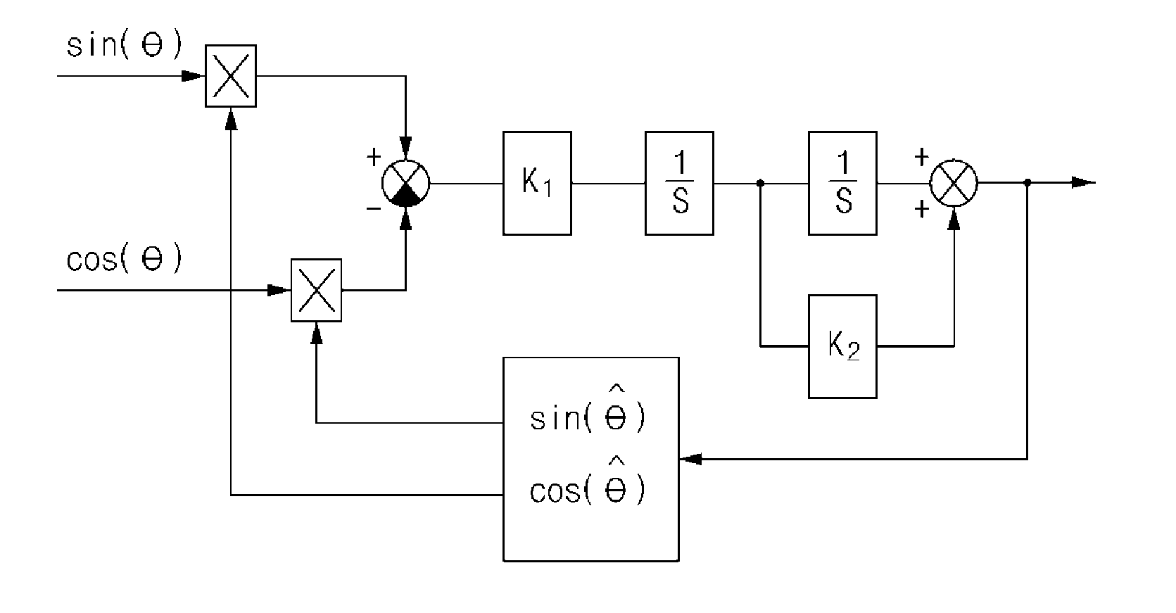
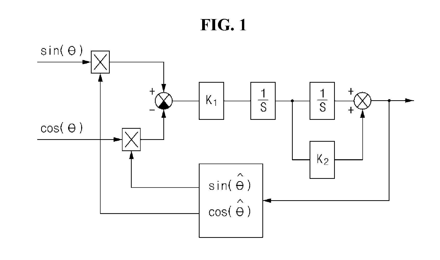
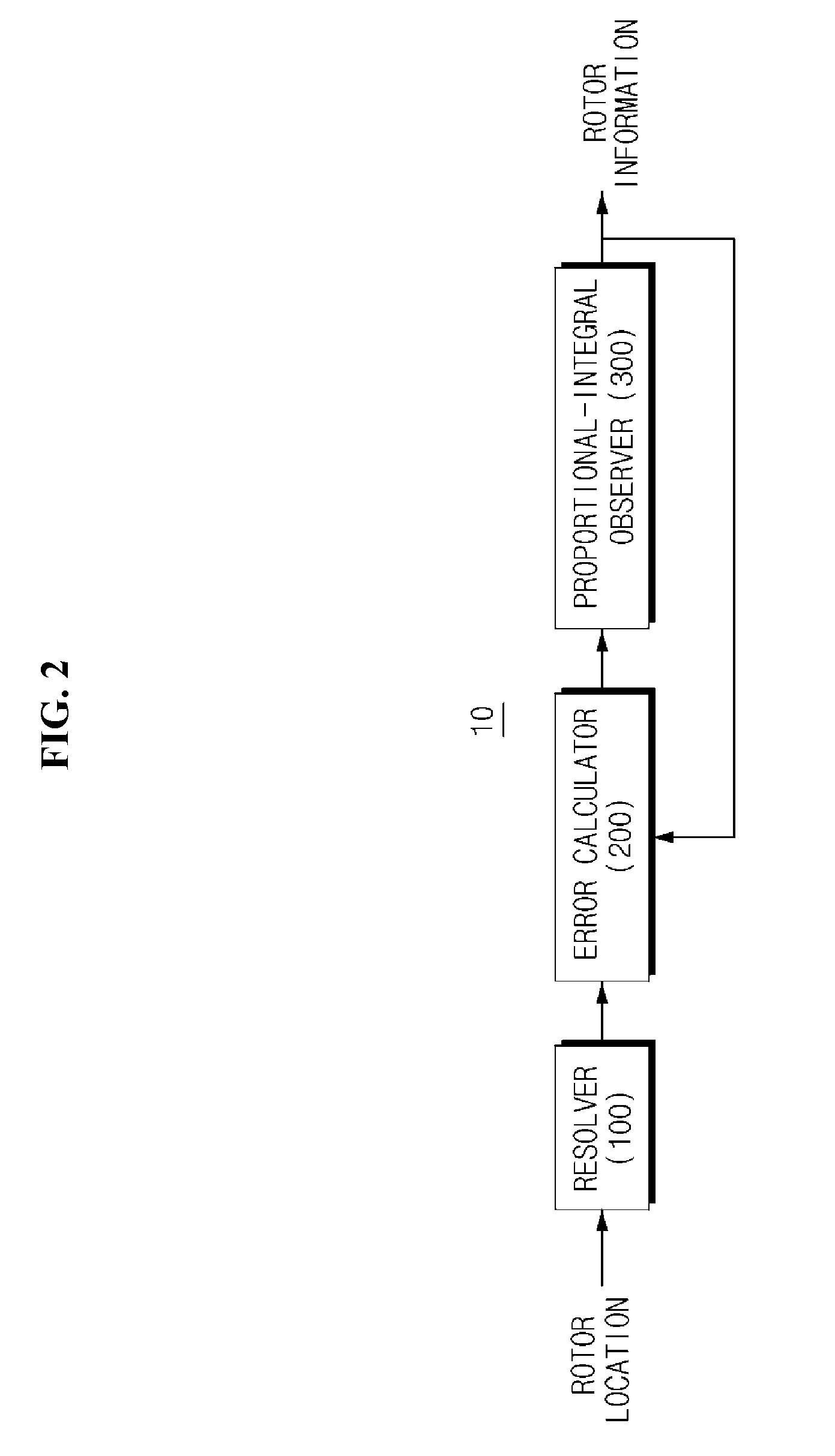
Disclosed is a rotor information estimation system including a resolver configured to measure a rotor location of a motor; a proportional-integral observer based on the motor and configured to estimate the rotor location of the motor; and an error calculator configured to calculate an error of the rotor location measured by the resolver using the rotor location estimated by the proportional-integral observer. The proportional-integral observer may estimate rotor information of the motor by performing an operation on the calculated error based on a characteristic of the motor.

Description

CROSS-REFERENCE TO RELATED APPLICATION[0001]This application claims priority from and the benefit of Korean Patent Application No. 10-2014-0157156 filed on Nov. 12, 2014, which is hereby incorporated by reference for all purposes as if fully set forth herein.BACKGROUND[0002]1. Field[0003]Exemplary embodiments relate to a rotor information estimation system.[0004]2. Discussion of the Background[0005]An alternating current (AC) motor control system is a system that is applied to a hybrid electric vehicle, an electric vehicle, and the like, and drives a vehicle and various devices of the vehicle by controlling an AC motor. The AC motor control system controls the AC monitor using rotor location information of the AC motor. The AC motor control system generally uses a resolver to obtain rotor location information.[0006]The resolver, a rotor location (angle) detector using an analog detection method, is mounted to a rotation shaft of the AC motor, measures a location of a rotor based on ...

Claims


Application Information

Patent Timeline
IPC IPC(8): H02P6/16G01D5/20
CPCG01D5/2006H02P6/16G01D5/2066
Inventor JEONG, GOO JONG
Owner HYUNDAI MOBIS CO LTD
Learn More