In-vessel and ex-vessel melt cooling system and method having the core catcher

a cooling system and core melt technology, applied in nuclear engineering, nuclear elements, greenhouse gas reduction, etc., can solve the problems of increasing construction costs, increasing the complexity of reactor operation and management, and reducing the economic efficiency of nuclear power plants, so as to improve the stability of the vessel and cool down the core melt so efficiently

Inactive Publication Date: 2016-05-19
KOREA ADVANCED INST OF SCI & TECH
View PDF4 Cites 19 Cited by
  • Summary
  • Abstract
  • Description
  • Claims
  • Application Information

AI Technical Summary

Problems solved by technology

One of the biggest radiation leakage accidents in the nuclear power plant is LOCA (Loss of Coolant Accident) that is characterized by radiation leakage by damage of pressure boundary in the reactor coolant system.
However, the operation of the active safety system including pumps and valves can increase the complexity in reactor operation and management and at the same time increases the construction expenses.
A powerful driving power is also necessary in order to run the active pump, which might reduce economical efficiency of the nuclear power plant.
When a critical accident happens in a nuclear power plant, the nuclear fuel in the core melts down and extremely high temperature melt emitting radiation ejected from the damaged nuclear reactor.
Then, the surrounding structures are eroded and the safety of workers is in danger, in addition to the worry about soil or water contamination.

Method used


Image

  • In-vessel and ex-vessel melt cooling system and method having the core catcher
  • In-vessel and ex-vessel melt cooling system and method having the core catcher
  • In-vessel and ex-vessel melt cooling system and method having the core catcher

Examples


Embodiment Construction

[0039]Hereinafter, the examples of the present invention are illustrated in detail with the attached figures. To give reference marks to the components of each figure, a same mark is given to the same components even if they are shown in different figures. In this description, if considered that a precise description on the related element or function is already well known to those in the art or may make it vaguer to understand, it would be omitted.

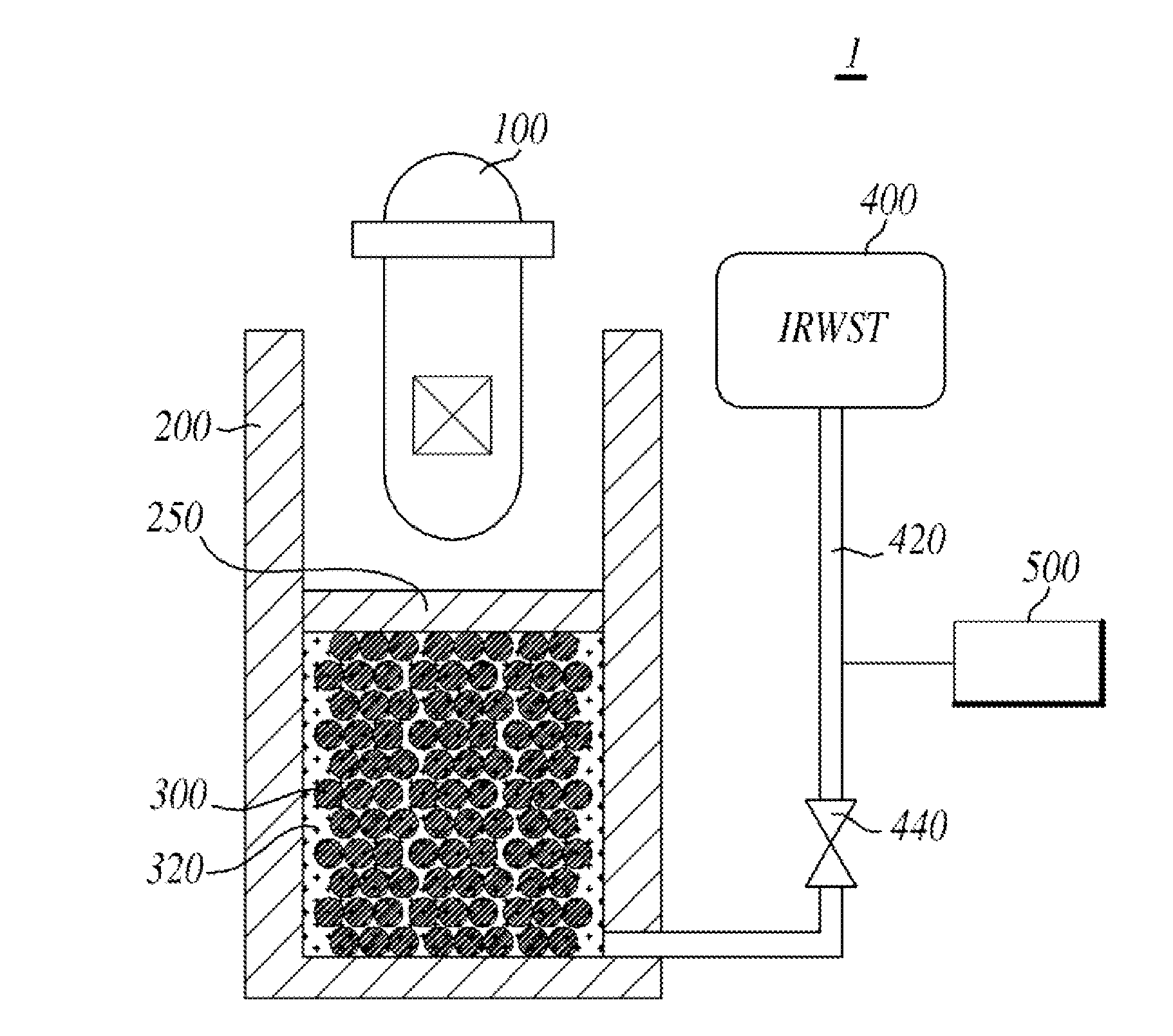
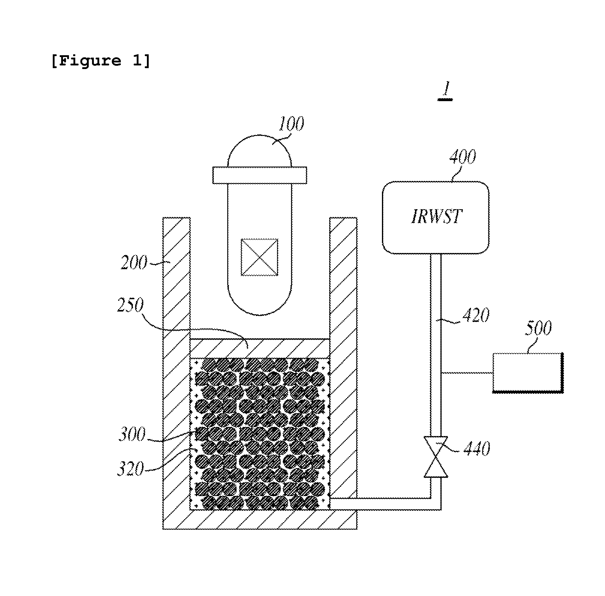
[0040]FIG. 1 is a schematic diagram illustrating the core melt cooling system according to an example of the present invention.

[0041]As shown in FIG. 1, the core melt cooling system (1) is to cool down the core melt ejecting from the damaged reactor vessel (100). The core melt cooling system (1) is able to cool down the core melt with the aid of the core catcher (300) and the coolant (320). The core melt cooling system (1) is for passive cooling, but the control of the coolant (320) is achieved actively.

[0042]The core melt cooling system ...


PUM


Abstract

The present invention relates to the in-vessel and ex-vessel melt cooling system having the core catcher. This system includes a reactor vessel having the core inside of the vessel, a core catcher that can cool the core melt ejecting from the damaged reactor vessel, a reactor cavity including the reactor vessel and the core catcher, IRWST (In-Containment Refueling Water Storage Tank) that can supply cooling water to the reactor cavity, and a control unit that can cut out the cooling water supply when the reactor cavity is filled with cooling water to the required level.

Description

BACKGROUND OF THE INVENTION[0001]1. Field of the Invention[0002]The present invention relates to a core melt cooling system, more precisely the in-vessel and ex-vessel melt cooling system and method having a core catcher.[0003]2. Description of the Related Art[0004]In general, a nuclear power plant is composed of more than 100 individual functional systems, which are largely divided into nuclear steam supply system including a nuclear reactor, a turbine that is running the generator with steam supplied from the said nuclear steam supply system, a generator system, and other appended facilities.[0005]In particular, the nuclear reactor is a multi-task apparatus that can generate heat by controlling fission chain reaction of a fissile material, produce radio-isotope and plutonium, or form a radiation field. The pressurized water reactor uses water as a moderator and a coolant, which is largely divided into two types according to the structural characteristics; a loop type reactor and a...

Claims


Application Information

Patent Timeline
Patent Type & Authority Applications(United States)
IPC IPC(8): G21C9/016G21C15/18
CPCG21C15/18G21C9/016Y02E30/30
Inventor NO, HEE CHEONPARK, BYUNG HA
Owner KOREA ADVANCED INST OF SCI & TECH
Why Eureka
Try Eureka