Protection circuit

a protection circuit and circuit technology, applied in the field of protection circuits, can solve the problems of increasing the scale of circuits, circuitry becoming complicated, and special processes, such as depletion-mode fet, to achieve the effect of small circuit size and low voltage resistan

Active Publication Date: 2016-05-19
CANON KK
View PDF2 Cites 5 Cited by
  • Summary
  • Abstract
  • Description
  • Claims
  • Application Information

AI Technical Summary

Benefits of technology

[0014]According to the present invention, it is possible to provide a protection circuit capable of passing a low-voltage signal as well as protecting internal circuitry which has low voltage resistance, from high voltages of both polarities, with a small circuit size and without requiring special processes.

Problems solved by technology

Firstly, there is the problem of increase in the scale of the circuitry.
In this case, the detection unit needs to have a high voltage resistance, and there is a problem in that since the drive circuit for operating the protection circuit is also necessary when configuring the protection circuit, then the circuitry becomes complicated.
Secondly, special processes, such as depletion-mode FET, become necessary.
However, this FET is problematic in that it requires special processing and costs increase.

Method used


Image

  • Protection circuit
  • Protection circuit
  • Protection circuit

Examples


first embodiment

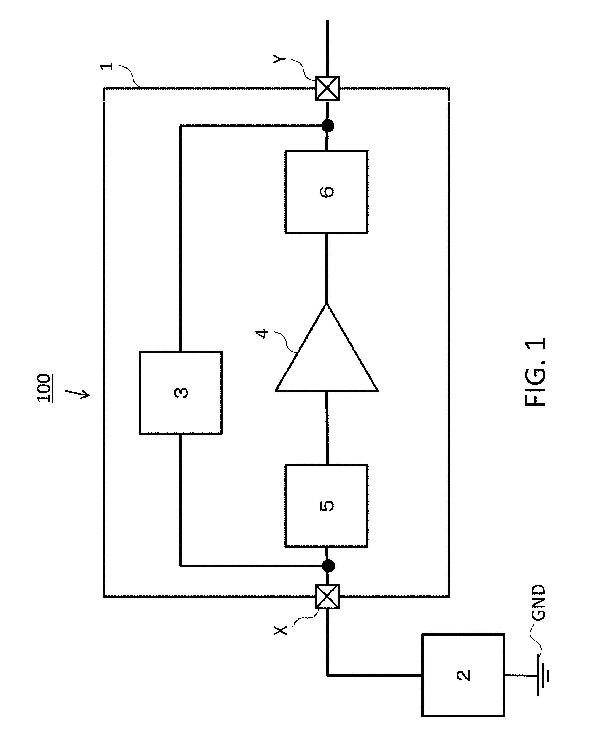
[0029]FIG. 1 is a block diagram showing a first embodiment of a protection circuit according to the present invention. The ultrasound diagnostic apparatus 100 (called “apparatus 100” below), which is an object information acquisition apparatus of the present embodiment, has a basic configuration of an ultrasound wave transmission and reception circuit 1 (abbreviated as “transmission and reception circuit 1” below) and an ultrasound wave transducer 2 (abbreviated as “element 2” below). The transmission and reception circuit 1 has a transmission circuit 3, a low-voltage amplification circuit 4, an input protection circuit 5 and an output protection circuit 6. The ultrasound wave transmission and reception circuit 1 is provided with external terminals X and Y, and signals are transmitted to and received from external apparatuses via the external terminals X and Y.

[0030]The transmission and reception circuit 1 refers to the whole circuit block of the ultrasound wave diagnostic apparatus...

second embodiment

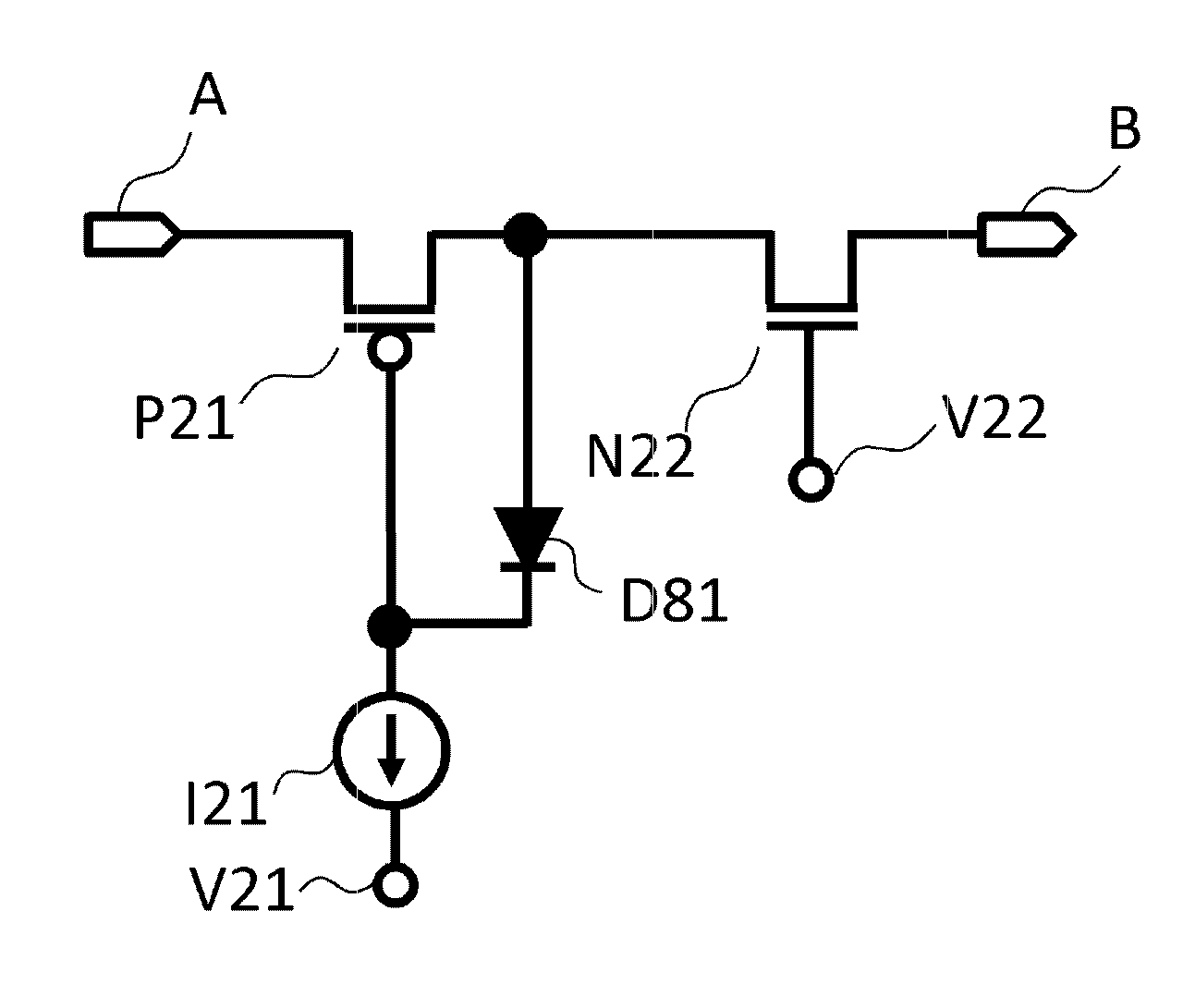
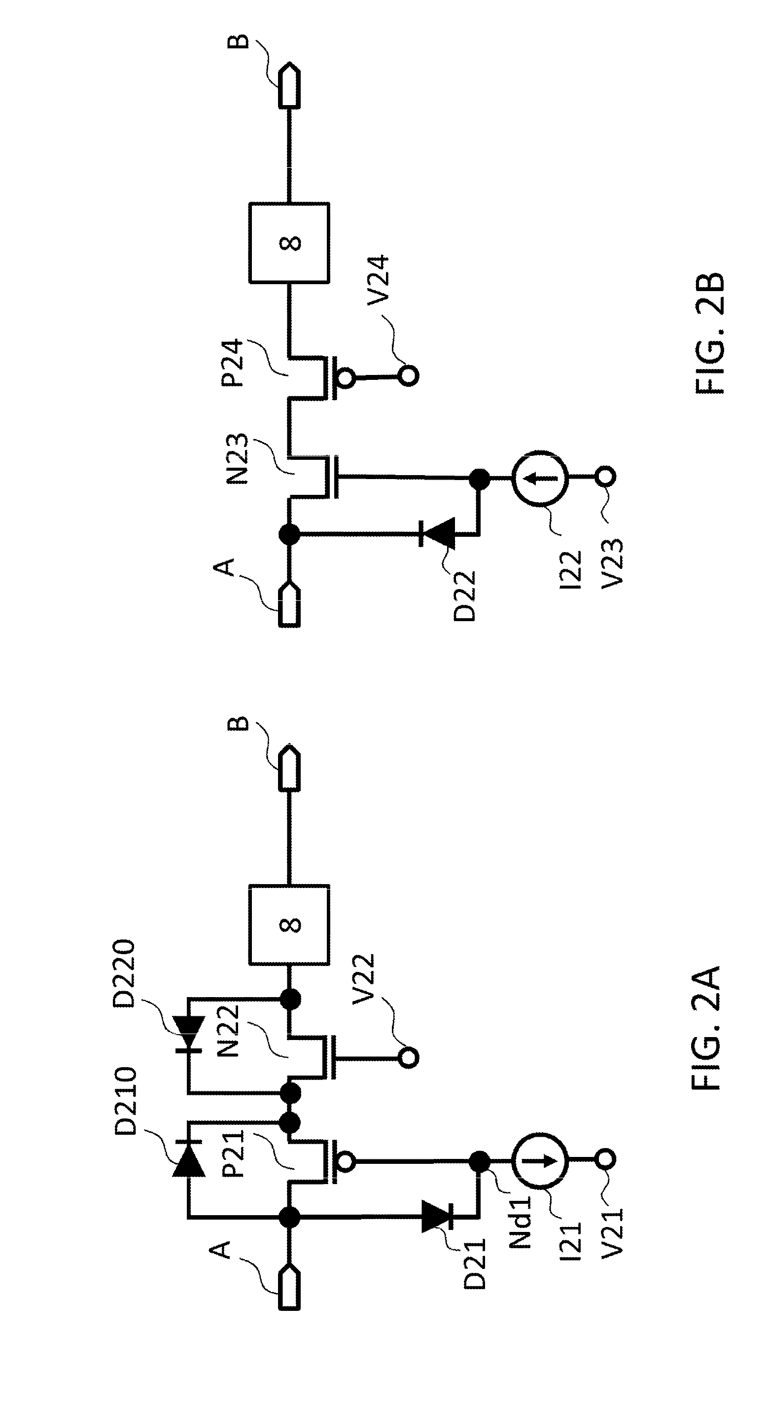
[0049]FIG. 8A and FIG. 8B are diagrams showing a second embodiment of a protection circuit in the ultrasound diagnostic apparatus according to the present invention, and constituent elements which are the same as FIG. 1 are labelled with the same reference numerals and description thereof is omitted apart from particular circumstances. The protection circuit of the present embodiment is configured such that the gate protection diodes D21, D22 in the protection circuits illustrated in FIGS. 2A and 2B of the first embodiment are connected to the sources of the transistors P21, N23, as in the diodes D81, D82 illustrated in FIGS. 8A and 8B. In this way, similarly to the first embodiment, the gate-source voltage of the transistors P21, N22 illustrated in FIGS. 8A and 8B is limited so as to become the threshold voltage of the diode D81, D82 (forward-direction voltage fall). By adopting this configuration, it is possible to prevent gate breakdown in the transistors P21 and N22. In the case...

third embodiment

[0050]FIG. 9A and FIG. 9B are diagrams showing a third embodiment of a protection circuit in the ultrasound diagnostic apparatus according to the present invention, and constituent elements which are the same as FIG. 1 are labelled with the same reference numerals and description thereof is omitted apart from particular circumstances. The protection circuit illustrated in FIGS. 9A and 9B of the present embodiment has a configuration in which the current sources I21, I22 of the protection circuit illustrated in FIG. 2A and FIG. 2B of the first embodiment are replaced with resistances R91 and R92.

[0051]The operation of the protection circuits illustrated in FIG. 9A and FIG. 9B is now described. The protection circuits illustrated in FIG. 9A and FIG. 9B have mutually reverse polarities but have the same basic function apart from this, and therefore the description is given here in relation to FIG. 9A only. When a low-voltage signal is applied to the terminal A, if the gate-source resis...


PUM


Abstract

A P-channel type MOSFET and an N-channel type MOSFET formed by a CMOS process are connected in series. A high-voltage signal and a low-voltage signal are applied to the drain of one of transistors. Prescribed bias voltage is applied to both gates in order that only a low-voltage signal can pass through both conduction paths.

Description

BACKGROUND OF THE INVENTION[0001]1. Field of the Invention[0002]The present invention relates to a protection circuit.[0003]2. Description of the Related Art[0004]An ultrasound transducer in an ultrasound diagnostic apparatus sends ultrasound waves on the basis of positive and negative high-voltage signals, and outputs a low-voltage signal obtained by receiving these very slight ultrasound waves, to a reception circuit. Therefore, a protection circuit which protects the amplifier circuit that amplifies the low-voltage signals output from the ultrasound transducer, against the high-voltage signals of both negative and positive polarity used to drive the ultrasound transducer, is required between the ultrasound transducer and the reception circuit which send and receive ultrasound waves. When a high-voltage signal is applied, this protection circuit switches off and thereby shuts off the high-voltage signal. Furthermore, when a low-voltage signal is applied, the circuit switches on to...

Claims


Application Information

Patent Timeline
Patent Type & Authority Applications(United States)
IPC IPC(8): H02H3/20A61B8/14A61B8/00H01L27/02H01L27/092
CPCH02H3/20H01L27/0266H01L27/0281A61B8/14H01L27/0296A61B8/56H01L27/092A61B8/4483B06B1/0207H03F1/523H02H9/046
Inventor MIKAJIRI, SATORU
Owner CANON KK
Why Eureka
Try Eureka