Biological information measuring apparatus

a technology of bioinformation and measuring equipment, applied in the field of biological information measuring equipment, can solve the problems of insufficient strength (durability) of the band, inability to release sweat and moisture outside, and discomfort experienced by wearers

Active Publication Date: 2016-05-26
SEIKO EPSON CORP
View PDF4 Cites 28 Cited by
  • Summary
  • Abstract
  • Description
  • Claims
  • Application Information

AI Technical Summary

Benefits of technology

[0013]An advantage of some aspects of the invention is to solve at least a part of the problems described above, and the invention can be implemented as the following forms or application examples.

Problems solved by technology

Therefore, if the apparatus is worn on the wrist for a long time, the wearer's sweat and inevitable moisture in living (for example, drops of water after washing the hands) accumulate between the bands and the skin, causing the problem of discomfort experienced by the wearer.
However, in the related-art apparatuses, if the groove shape is not properly set, there is a risk that the sweat and moisture cannot be released outside sufficiently or that the strength (durability) of the bands may not be sufficient.
Specifically, if the width of the groove is too narrow or the depth of the groove is too shallow, it is difficult for the sweat and moisture to escape outside from the tight contact part between the bands and the skin, and consequently the sweat and moisture remaining in the tight contact part between the bands and the skin cause discomfort to the wearer.
In other words, the sensation of wearing experienced by the wearer is impaired and the wearer ends up feeling stressed about long-time wearing.
In some cases, the wearer may give up wearing the apparatus.
Also, if the width of the groove is narrow or the depth of the groove is shallow, the flexibility of the bands is impaired.
Therefore, the durability with time of the bands may fall and damage such as cracking may occur.
Meanwhile, if the width of the groove is too broad or the depth of the groove is too deep, the strength of the bands falls, leading to damage to the bands, or deformation of the bands due to an impact or acceleration (G) applied to the apparatus at the time of running, for example.
Consequently, biological information (health state) such as the pulse waves of the wearer can no longer be measured (grasped) accurately.

Method used


Image

  • Biological information measuring apparatus
  • Biological information measuring apparatus
  • Biological information measuring apparatus

Examples


embodiment 1

Outline of Biological Information Measuring Apparatus

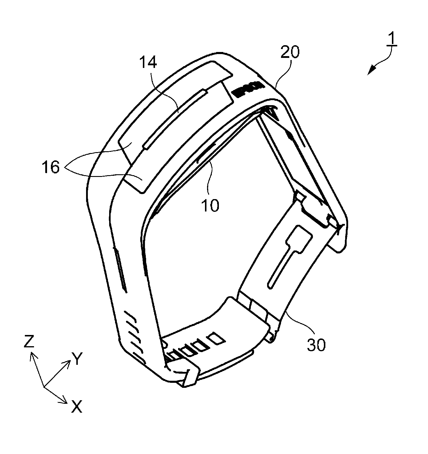
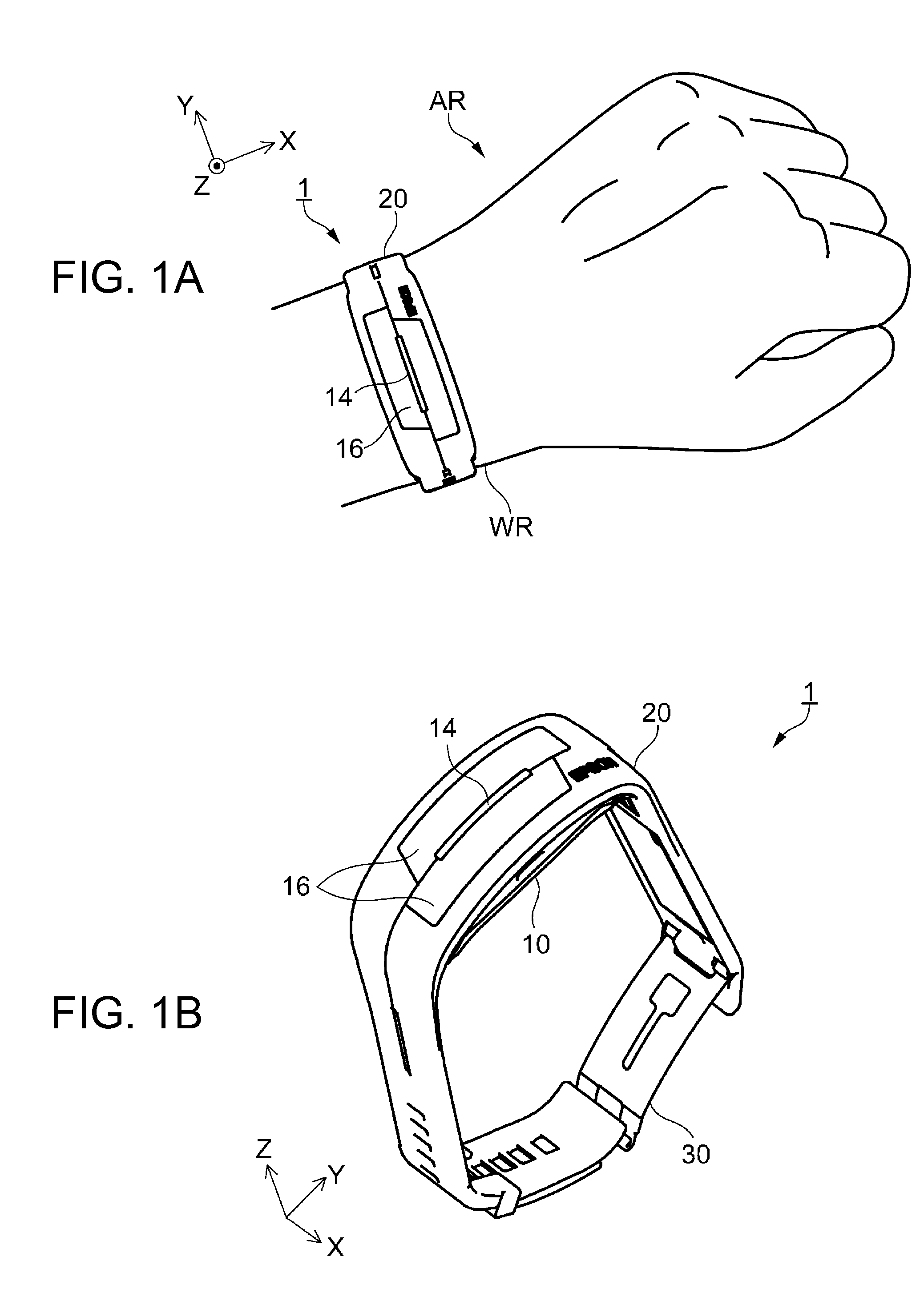
[0065]FIGS. 1A and 1B show the schematic configuration of a biological information measuring apparatus according to Embodiment 1. FIG. 1A shows a wearing state where the biological information measuring apparatus is installed on a living body. FIG. 1B shows an open state where the biological information measuring apparatus is removed from the living body.

[0066]A biological information measuring apparatus (hereinafter also referred to as a measuring apparatus) 1 according to this Embodiment 1 is an electronic apparatus which is installed on a living body (for example, a human body) whose biological information is measured, and which measures biological information such as pulse waves. As shown in FIG. 1A, the measuring apparatus 1 is installed at a measuring site (wrist or the like) of the wearer (living body) like a wristwatch and used in this state. In the embodiment, the state where the measuring apparatus 1 is installed on the ...

modification 1

[0142]In Modification 1 shown in FIG. 11A, a plurality of groove parts 28 is provided on the first band part 22, along a direction (X-axis direction) intersecting with the direction of extension of the band 20 (Y-axis direction) and arranged next to each other at substantially the same interval in the Y-axis direction. Here, the width W10 and the depth D1 (not shown) of the groove parts 28 are configured to be similar to those in the first embodiment. The interval between the groove parts 28 may not necessarily be substantially the same. For example, the interval may be narrowed sequentially as it goes from the side of the case unit 10 (see FIGS. 1A and 1B) toward the distal end, or the interval may be narrowed and the number of groove parts 28 may be increased at the site in tight contact with the wrist WR so as to improve ventilation.

[0143]With such groove parts 28 according to Modification 1 provided, for example, when the measuring apparatus is installed on a curved surface such...

modification 2

[0144]In Modification 2 shown in FIG. 11B, a first groove part 28a extending along the direction of extension of the band 20 (Y-axis direction) is provided at a center part in the direction of the width of the first band part 22 (X-axis direction), and a plurality of second groove parts 28b extending along two directions intersecting the first groove part 28a (in this example, XY-direction and −XY-direction) and arranged next to each other in the Y-axis direction are provided. The first groove part 28a and the second groove parts 28b are connected together and thus configured in a so-called lattice form (mesh form). Here, the width W10 and the depth D1 (not shown) of the first groove part 28a and the second groove parts 28b are configured to be similar to those in the first embodiment. Also, a plurality of first groove parts 28a may be provided. The number of the second groove parts 28b may be one or more. Moreover, the second groove parts 28b in a single direction (for example, fro...


PUM


Abstract

A biological information measuring apparatus (measuring apparatus) includes a band which fixes a case unit to a living body. The band is provided with a recessed groove part on a side facing the living body. The groove part has a depth of 1020 μm or more and 1140 μm or less.

Description

[0001]This application claims priority to Japanese Patent Application No. 2014-235329, filed Nov. 20, 2014, the entirety of which is hereby incorporated by reference.BACKGROUND[0002]1. Technical Field[0003]The present invention relates to a biological information measuring apparatus.[0004]2. Related Art[0005]According to the related art, a measuring apparatus which is installed at a site such as the wrist with a band or the like and measures biological information such as the pulse waves and pulse rates of the wearer, and a wristwatch-like electronic apparatus having the function of measuring such biological information, are known (see, for example, JP-A-2010-110634 and JP-A-2006-271610). In the case of such apparatuses (measuring apparatus and electronic apparatus), a case unit (main body unit) having a display unit is installed on the wrist with two bands extending on both sides of the case unit. On the back side of the case unit (opposite side of the display unit), a detection un...

Claims


Application Information

Patent Timeline
Patent Type & Authority Applications(United States)
IPC IPC(8): A61B5/00
CPCA61B2562/164A61B5/681A61B5/002A61B5/02416A61B5/02438A61B5/721A61B2562/0219
Inventor INAGAKI, AKIRA
Owner SEIKO EPSON CORP
Why Eureka
Try Eureka