Laser system for tissue ablation

a laser system and tissue ablation technology, applied in the field of medicine and dentistry, can solve the problems of unpleasant and potentially unsafe effects of laser light emission, affecting the safety of patients, and emitted high intensity visible and ultraviolet light, and achieve the effect of avoiding overheating of laser material

Active Publication Date: 2016-05-26
FOTONA D O O
View PDF1 Cites 29 Cited by
  • Summary
  • Abstract
  • Description
  • Claims
  • Application Information

AI Technical Summary

Benefits of technology

[0030]Maintaining these upper limits for the pulse duration and consequently for the number of maxima per pulse avoids overheating of the laser material and also of the treated tissue. And maintaining the aforementioned lower limit of the pulse duration T0 avoids the high average intensities and large debris cloud densities that are characteristic for laser pulses of short duration.

Problems solved by technology

The laser absorption leads to local heating with sudden evaporation that causes material removal.
For most medical procedures this “hot” regime is not desirable, since it may result in thermal tissue necrosis.
As a result, pulsed laser ablation is typically accompanied by undesirable high intensity visible and UV light being emitted from the debris cloud area.
All these accompanying effects are unpleasant and potentially unsafe for the practitioner and the patient.
On the other hand, the undesirable effects of the interaction of the laser light with the debris cloud are much less pronounced at longer pulse durations 350 microseconds) and lower pulse intensities.

Method used


Image

  • Laser system for tissue ablation
  • Laser system for tissue ablation
  • Laser system for tissue ablation

Examples


Embodiment Construction

[0039]Some of the embodiments of the invention will be explained in the following with the aid of the drawings in more detail. It is shown in:

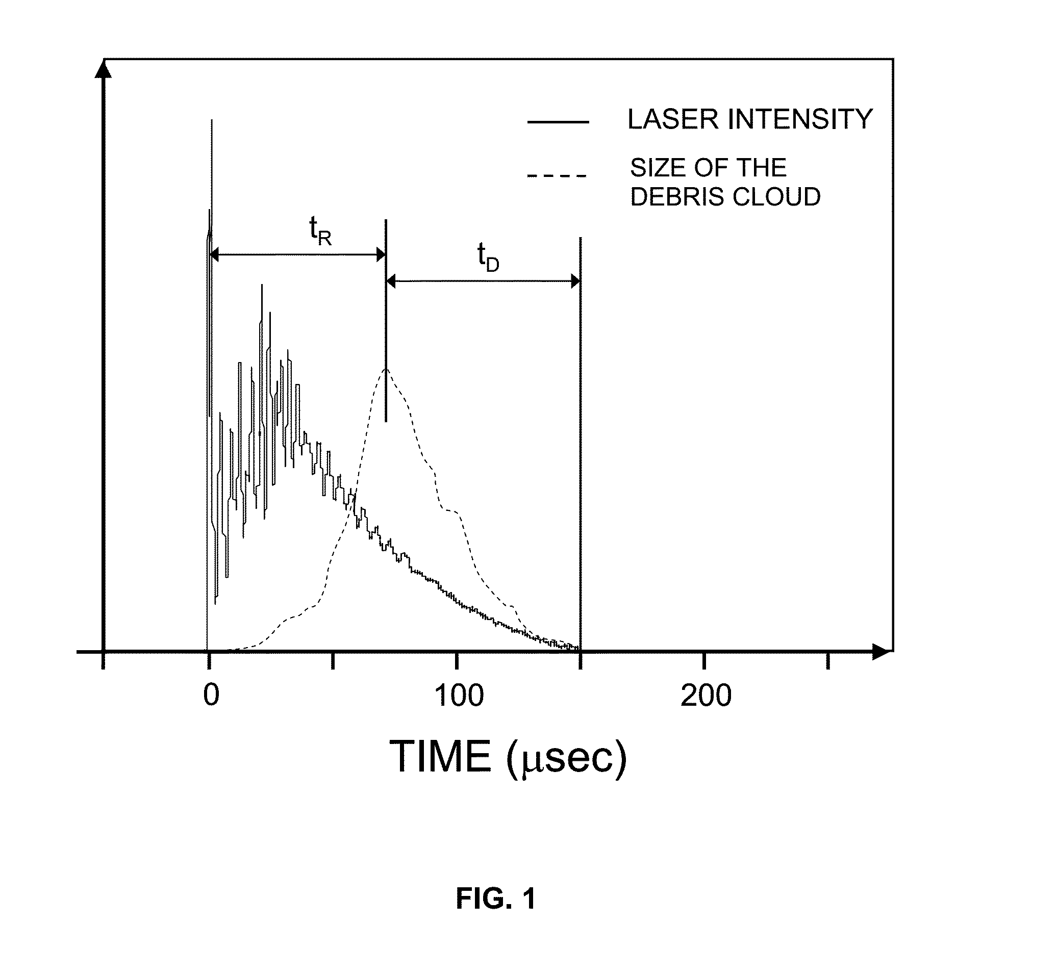
[0040]FIG. 1 a diagrammatic illustration of the temporal laser intensity and the temporal debris cloud development during the course of a laser pulse;

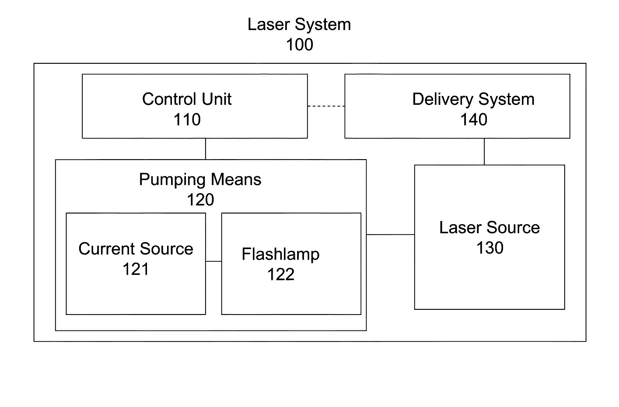
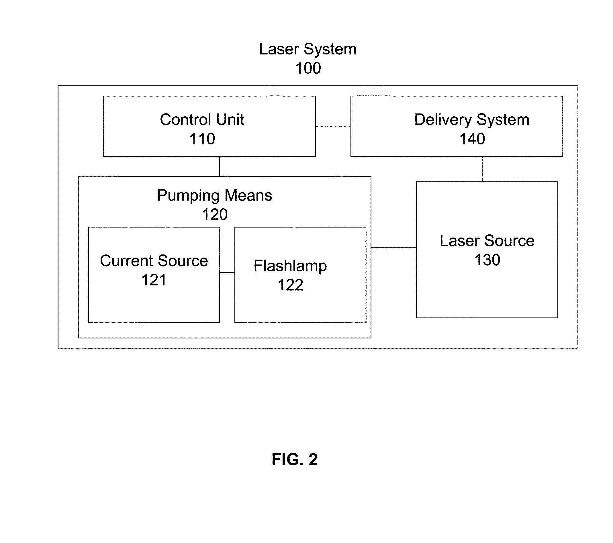
[0041]FIG. 2 a laser system according to the invention;

[0042]FIG. 3 a schematic illustration which shows the difference between the temporal development of the laser intensity according to the prior art and the temporal development of the laser intensity according to the present invention;

[0043]FIG. 4 an exemplary flash lamp current according to the present invention and the intensity of the laser pulse which is generated by the flash lamp current;

[0044]FIG. 5 in a diagrammatic illustration the temporal development of the pump-forced pulse intensity modulation according to the present invention;

[0045]FIG. 6 in a diagrammatic illustration the temporal development of a pump-forced pulse intensity m...


PUM

PropertyMeasurementUnit
rise timeaaaaaaaaaa
decay timeaaaaaaaaaa

Abstract

A Laser system is disclosed which comprises a pump, wherein the laser system is adapted to be operated in pulsed operation so that at least one individual pulse of a temporally limited pulse duration (T0) is generated, wherein the pulse ablates a material such that a debris cloud forms above the ablated material. Further, the pump power of the pump is modulated in such a way that the following three conditions are fulfilled: (1) the intensity of the pulse oscillates between maximum values and minimum values during the pulse duration, wherein the laser pulse comprises a plurality of intensity maxima Imax which occur at times {Ti, i=1, . . . N}; and a plurality of intensity minima Imin which occur at times {tk, k=1, . . . (N−1)}, wherein the intensity does not vanish at the intensity minima; (2) the intensity oscillations of the laser pulse induce oscillations of the size of the debris cloud so that, during the pulse duration (T0), there are at least two maxima of the size of the debris cloud which occur at times {tj, J=1, . . . M} and which are located in between two intensity maxima of the laser pulse; and (3) at least 70 percent of the maxima of the size of the debris cloud occur near an intensity minimum of the pulse such that, for at least 70 percent of the maxima of the size of the debris cloud, the intensity of the pulse I(tj) at the time of the maximum of the size of the debris cloud is smaller than Imin(tk)+0.5× [Imax(Ti)−Imin(tk)], wherein Imin(tk) is the intensity minimum of the pulse which is closest to the maximum of the size of the debris cloud at time tj and Imax(Ti) is the intensity maximum of the pulse which is closest to the maximum of the size of the debris cloud at time tj.

Description

TECHNICAL BACKGROUND[0001]In the field of medicine, dentistry or the like, pulsed lasers are used for the removal of hard and soft body tissues such as dental enamel, dentine, bone material, skin and mucosa. The material removal in tissue ablation is based on a pronounced absorption of the temporally limited laser pulse in the ablated tissue. The laser absorption leads to local heating with sudden evaporation that causes material removal.[0002]Depending on the laser intensity I (optical power per unit area) two distinct ablation regimes can be encountered in pulsed laser ablation. At low intensities, the speed of ablation is lower than the speed at which the laser-generated heat diffuses away from the ablated surface area deeper into the tissue. In this regime, the thermally influenced layer of tissue that is not ablated by the end of the laser pulse is relatively thick. For most medical procedures this “hot” regime is not desirable, since it may result in thermal tissue necrosis.[0...

Claims


Application Information

Patent Timeline
Patent Type & Authority Applications(United States)
IPC IPC(8): H01S3/11A61B18/20H01S3/092
CPCH01S3/11H01S3/092A61B18/20A61B2017/00185A61B2018/00577A61B2018/00642A61B2018/00029B23K26/0626A61B2017/00159B23K26/0622H01S3/1024
Inventor MARINCEK, MARKONENDL, JANKOMOCNIK, MATJAZMATJAZ, LUKAC
Owner FOTONA D O O
Why Eureka
Try Eureka