Systems and methods for manufacture of dimethyl ether (DME) from natural gas and flare gas feedstock

a technology of dimethyl ether and natural gas, which is applied in the field of systems and methods for manufacturing dimethyl ether (dme) from natural gas and flare gas feedstock, can solve the problems of high cost of methanol, low economic and environmental benefits, and low production efficiency, and achieves significant environmental and economic benefits. , the effect of enhancing the economic and energy security of the world and reducing imports

Active Publication Date: 2016-06-02
PIONEER ENERGY
View PDF4 Cites 10 Cited by
  • Summary
  • Abstract
  • Description
  • Claims
  • Application Information

AI Technical Summary

Benefits of technology

[0017]The DImethyl Ether from Methane (“DIEM”) system would allow dimethyl ether, a diesel substitute, to be produced from low value natural gas, or even from currently wasted flare gas, at a cost substantially lower than petroleum-based diesel. DME can be used at 100% substitution on an unmodified diesel engine, utilizing 60-100 psi propane-rated storage tanks DME is a sulfur-free, particulate-free, ultra-clean diesel fuel, that can be put directly to use without further refinement. Using surplus natural gas and flare gas for liquid fuel production yields significant environmental and economic benefits. The process would enhance the economic and energy security of the world through: a) reductions of imports of energy from volatile regions of the world; b) reductions in energy-related emissions, including greenhouse gases; and c) improvement in the energy and economic efficiency of the oil and gas sector.
[0018]The inventors have thus developed a unique design for a mobile system that reforms flare gas or natural gas, using air without steam, to directly produce dimethyl ether (DME), a diesel substitute. The system first reforms the air-methane mixture at pressures close to ambient pressure, preferably at ambient pressure, and then compresses the resulting CO-hydrogen-nitrogen gas mixture to high pressures in the 100-2000 psi range, preferably at around 300 psi and feeds the gas mixture through a combined reactor which reacts the gas mixture directly into dimethyl ether. The nitrogen is returned by the system back to the atmosphere. DME is an excellent diesel fuel, and can be used to displace significantly costlier and dirtier petroleum-based diesel fuel, while solving a critical problem with flaring and stranded gas.
[0019]Existing competing technologies for dealing with stranded natural gas include hauling the flare gas by truck as CNG or LNG. These solutions are inferior to the DIEM because of the logistical complexity and cost of transporting CNG and LNG compared to transporting a room temperature liquid such as DME produced on site by the DIEM. Alternatively, DME today is currently produced in massive stationary industrial scale chemical plants, which must be supplied with pipeline natural gas or coal, which are commercial feedstocks that can be expensive, as opposed to flare gas, which is free and a hindrance. Furthermore, making DME out of marketable fuels does nothing to reduce flaring or CO2 emissions. Systems that make methanol out of flare gas have frequently been proposed, but such systems require steam and oxygen, making their product methanol expensive. Thus, the DIEM is uniquely advantageous. By using the DIEM, the over 120 billion cubic feet per year that is currently flared in North Dakota could be converted into over 3 million tons of DME.

Problems solved by technology

These solutions are inferior to the DIEM because of the logistical complexity and cost of transporting CNG and LNG compared to transporting a room temperature liquid such as DME produced on site by the DIEM.
Furthermore, making DME out of marketable fuels does nothing to reduce flaring or CO2 emissions.
Systems that make methanol out of flare gas have frequently been proposed, but such systems require steam and oxygen, making their product methanol expensive.

Method used


Image

  • Systems and methods for manufacture of dimethyl ether (DME) from natural gas and flare gas feedstock
  • Systems and methods for manufacture of dimethyl ether (DME) from natural gas and flare gas feedstock
  • Systems and methods for manufacture of dimethyl ether (DME) from natural gas and flare gas feedstock

Examples


Embodiment Construction

[0068]The following description is merely exemplary in nature and is in no way intended to limit the scope of the present disclosure, application, or uses.

Definitions

[0069]The following terms are provided for illustrative and explanatory purposes only, and are not intended to limit the application, intended uses, or scope of the present invention.

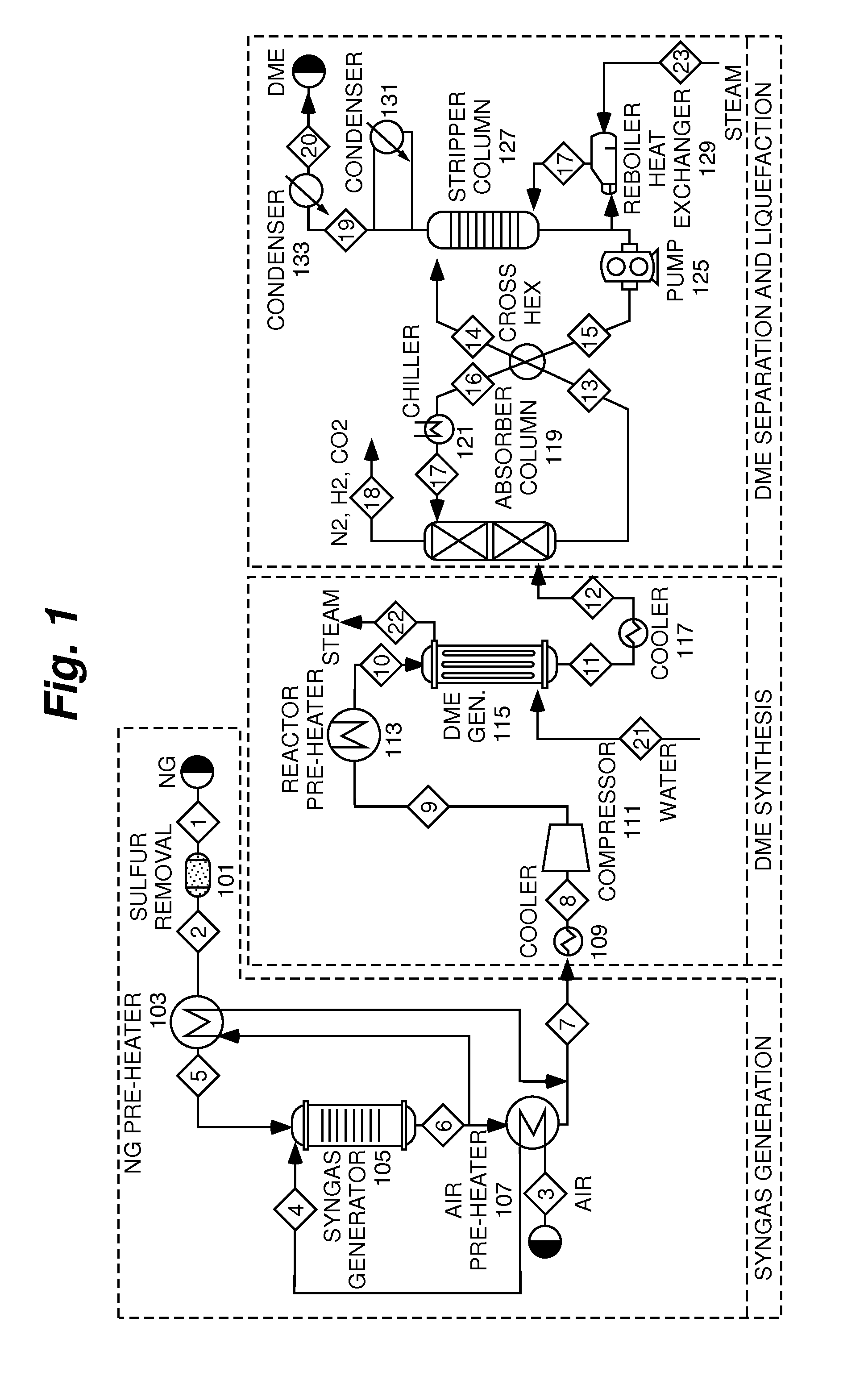
[0070]Throughout this disclosure “DIEM-170,”“full scale” apparatus, or any reference to a single full-scale module, will refer to an apparatus module that can process about 170 mcf (thousand cubic feet) of raw natural gas per day. Multiple modules can be combined for higher gas flow rates. These product flow estimates are provided for explanation purposes only, and are not intended to be limiting the scope of the present invention in any way. DIEM is a shorthand for “DImethyl Ether from Methane” system.

[0071]The symbols cf, CF, scf, and SCF shall all stand for standard cubic feet (ft3). The symbols mcf, MCF, and kcf will all stand for a tho...


PUM

PropertyMeasurementUnit
pressuresaaaaaaaaaa
pressuresaaaaaaaaaa
pressuresaaaaaaaaaa

Abstract

A unique design for a mobile system that reforms flare gas or natural gas, using air without steam, to directly produce dimethyl ether (DME), a diesel substitute, is disclosed. The system first reforms the air-methane mixture at ambient atmospheric pressures, and then compresses the resulting CO-hydrogen-nitrogen gas mixture to up to 600 psi, and feeds it through a combined reactor which reacts the gas mixture directly into dimethyl ether. The nitrogen is returned by the system back to the atmosphere. DME is an excellent diesel fuel, and can be used to displace significantly costlier and dirtier petroleum-based diesel fuel, while solving a critical problem with flaring. For example, the over 120 billion cubic feet per year that is currently flared in North Dakota could be converted into over 3 million tons of DME.

Description

REFERENCE TO RELATED APPLICATIONS[0001]This application claims the benefit of provisional application U.S. Ser. No. 62 / 085,391, filed on 28 Nov. 2014, and entitled “DIMETHYL ETHER (DME), A DIESEL-SUBSTITUTE LIQUID FUEL, FROM NATURAL GAS AND FLARE GAS FEEDSTOCK,” which is incorporated by reference in its entirety herein.FIELD OF THE INVENTION[0002]The present invention relates to enabling the utilization of raw natural gas, such as flare gas, stranded gas, associated gas, and so on, for dimethyl ether (DME) production. More specifically, this invention relates to a mobile system for producing DME from any natural gas feedstock, wet or dry.BACKGROUND OF THE INVENTION[0003]The statements in this section merely provide background information related to the present disclosure and may not constitute prior art.[0004]The U.S. is currently flaring so much stranded natural gas that the gas flares are visible from outer space. The world as a whole annually flares about 5,000 billion cubic feet...

Claims


Application Information

Patent Timeline
Patent Type & Authority Applications(United States)
IPC IPC(8): C07C41/34C07C41/09C01B3/36B01J8/02
CPCC07C41/34B01J8/02C07C41/09C01B2203/1258B01J2208/025C01B2203/1241C01B2203/06C01B3/36C07C41/42C01B3/386C01B2203/0261C07C29/1518Y02P20/129
Inventor ZUBRIN, ROBERT M.NIZAMOV, BORISHENSHAW, THOMAS LKORTAN, ADAM MSIEBARTH, JAMESAPKE, COLINBERGGREN, MARK
Owner PIONEER ENERGY
Why Eureka
Try Eureka