Valve device with a valve based on an electrodynamic actuator and method for controlling a valve with an electrodynamic actuator

a valve device and actuator technology, applied in the direction of valve details, electrical devices, electromagnets, etc., can solve the problems of disturbance of pulses in fluid streams, and achieve the effect of simplifying maintenance and exchange of front-end electronic units and being handled more easily

Active Publication Date: 2016-06-02
BURKERT WERKE
View PDF1 Cites 3 Cited by
  • Summary
  • Abstract
  • Description
  • Claims
  • Application Information

AI Technical Summary

Benefits of technology

[0010]According to a first embodiment of the valve device, the front-end electronic unit provided according to the invention is a unit constructionally separate from the valve. A separate front-end electronic unit has the advantage that it can be offered as an option to the actual valve. In addition, adaptation as well as maintenance and exchange of the front-end electronic unit are simplified.
[0011]The front-end electronic unit can, however, also be integrated into the electrodynamic actuator of the valve. The device thereby becomes distinctly more compact and can be handled more easily. The integration of the front-end electronic unit generally is unproblematic, as only few electrical components—in the simplest case only a suitably designed capacitor—must be accommodated in the housing of the actuator.

Problems solved by technology

Especially in the field of microfluidics, a high number of successive water hammers of conventional valves can lead to disturbing pulses in the fluid stream in the connected fluidic line.

Method used


Image

  • Valve device with a valve based on an electrodynamic actuator and method for controlling a valve with an electrodynamic actuator
  • Valve device with a valve based on an electrodynamic actuator and method for controlling a valve with an electrodynamic actuator
  • Valve device with a valve based on an electrodynamic actuator and method for controlling a valve with an electrodynamic actuator

Examples


Embodiment Construction

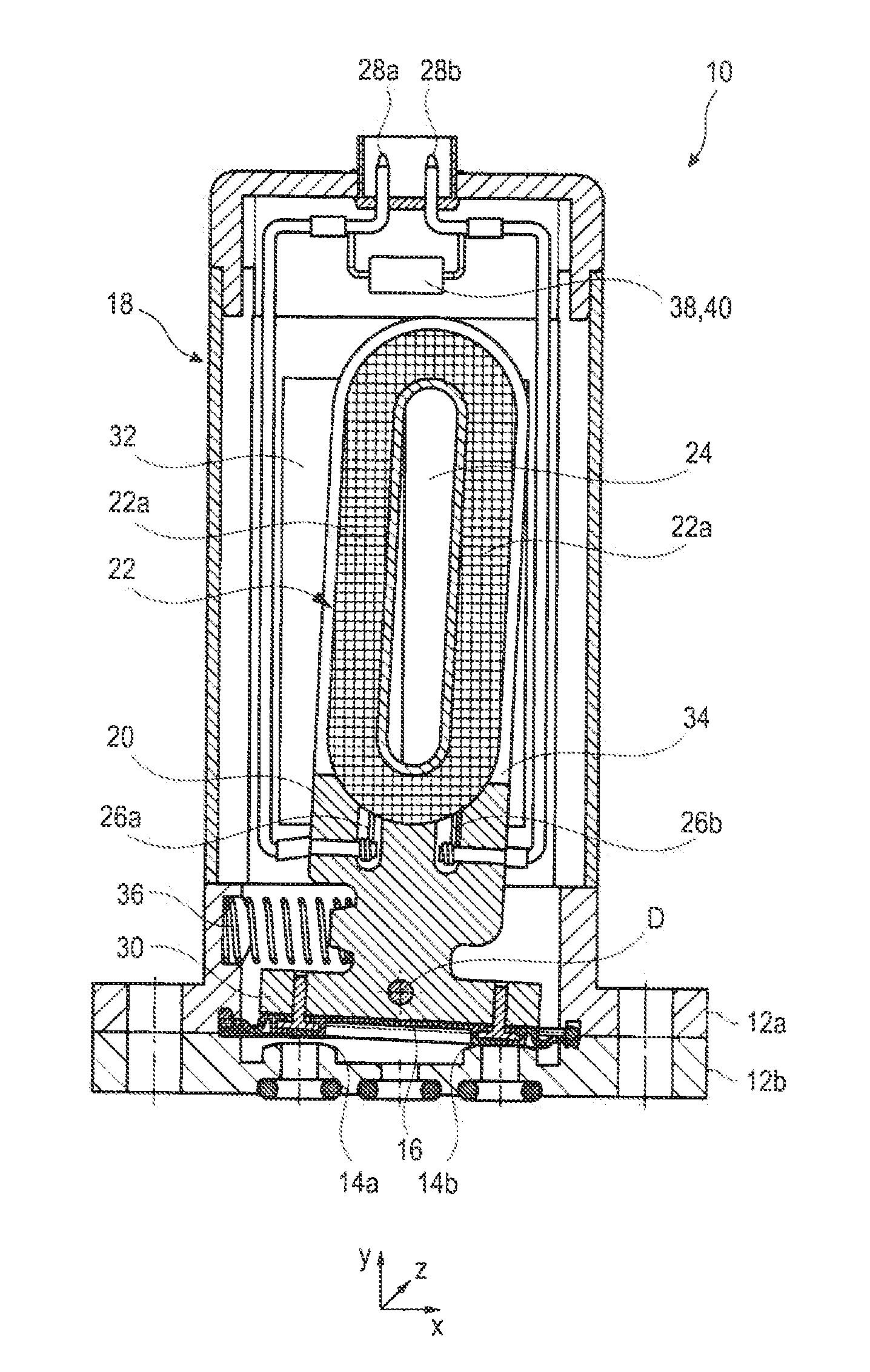
[0031]FIG. 1 by way of example shows an embodiment of a media-separated valve 10, here a micro valve, with an electrodynamic actuator. The electrodynamic actuator is put onto a two-part fluid housing 12a, 12b, in which two valve seats 14a, 14b located one beside the other are formed. The valve seats 14a, 14b can alternately be opened or closed by a membrane 16 clamped between the housing halves 12a, 12b or by stamps or other sealing elements inserted therein.

[0032]The electrodynamic actuator comprises an actuator housing 18 in which a movable control element and an immovable magnet arrangement are accommodated. The control element substantially is formed of a coil carrier 20 of a non-magnetic material and a coil 22 of a copper wire wound onto the coil carrier 20 or otherwise firmly connected with the same, i.e. the coil carrier 20 and the coil 20 always move together.

[0033]The coil 22 comprises a plurality of windings around a non-soft-magnetic core 24 (air or another non-magnetic m...


PUM

PropertyMeasurementUnit
switching timeaaaaaaaaaa
current intensityaaaaaaaaaa

Abstract

A valve device includes a valve having an electrodynamic actuator. The electrodynamic actuator includes a movably mounted control element having a coil and a magnet arrangement immovable relative to the coil. A driving force caused by energization of the coil and transmitted to the control element substantially is linearly dependent on the current intensity. A front-end electronic unit is connected with the coil and includes a capacitor connected in parallel to the coil. A method for controlling a valve as mentioned above provides that, upon actuation of the electrodynamic actuator, during energization of the coil by a voltage source, a capacitor connected in parallel to the coil is charged. After termination of the energization by the voltage source, the coil is energized further by a discharge of the capacitor.

Description

TECHNICAL HELD[0001]The invention relates to a valve device which comprises a valve with an electrodynamic actuator. The invention furthermore relates to a method for controlling a valve with an electrodynamic actuator.BACKGROUND OF THE INVENTION[0002]With the increasing demands in apparatus engineering, the demands on the valves used therein also are increasing. In modern laboratories, for example, and in particular in the clinical area directly in the patient environment, the avoidance or reduction of noise pollution gains in importance more and more. Especially for the field of “media-separated” valves, as they are used e.g. in food, analysis, laboratory and medical technology, only few low-noise solutions do exist on the market.[0003]For many of the above-mentioned applications, solenoid valves are the first choice from a technical point of view. They are designed for fast cycle duties and with a corresponding design are suitable for aggressive or neutral liquid and gaseous medi...

Claims


Application Information

Patent Timeline
Patent Type & Authority Applications(United States)
IPC IPC(8): F16K31/06H01F7/08
CPCF16K31/0644H01F7/08F16K31/0675F16K31/0682F16K31/082H01F7/066H01F7/1816H01F2007/1822
Inventor FUCHS, MAIKSCHEIBE, RALFKAHL, SEBASTIAN
Owner BURKERT WERKE
Why Eureka
Try Eureka