Scintillation Detector and Method for Forming a Structured Scintillator

a detector and structured technology, applied in the direction of instruments, x/gamma/cosmic radiation measurement, radiation intensity measurement, etc., can solve the problems of high cost of structured phosphor products, so as to improve the manufacturability of forming structured scintillators, eliminate the effect of scattering

Inactive Publication Date: 2016-06-02
STC MT
View PDF25 Cites 10 Cited by
  • Summary
  • Abstract
  • Description
  • Claims
  • Application Information

AI Technical Summary

Benefits of technology

[0033]A distinctive feature of the proposed group of inventions is a new method of forming a structured scintillator on the surface of a pixelated photodetector, wherein, in particular, a two-axis or a three-axis means is used for the discrete deposition of homogeneous liquid or heterogeneous substances for depositing directly to the photodetector surface the material of at least one structural element of the scintillator, which improves the manufacturability of the proposed method that allows forming many various designs of the scintillator, the structural elements of various shapes with a various heterogeneous structure, as well as depositing and aligning scintillation structures on non-recurrent or different-dimensional photodetector arrays, thus simultaneously extending the scope of its application. The main advantage of the proposed method is the possibility of permanent elimination of the need for pr

Problems solved by technology

The essential problem of the “screen-photodetector” stack is an optical scattering provokes the partial exposure of image areas (pixels) by the light from adjacent areas.
An accurate alignment of the array photodetector structure with a scintillator structure divided into pixel areas of the screen is one of the main technically complicated and technologically time-consuming tasks.
The equipment needed for the purpose of such an alignment and the value of its depreciation signif

Method used


Image

  • Scintillation Detector and Method for Forming a Structured Scintillator
  • Scintillation Detector and Method for Forming a Structured Scintillator
  • Scintillation Detector and Method for Forming a Structured Scintillator

Examples


embodiment 1

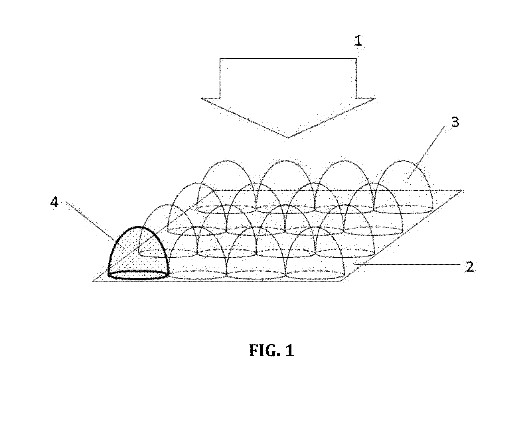
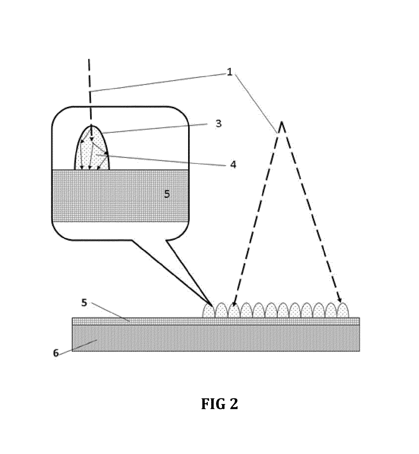
[0042]FIG. 1 shows a general view of the structure of the scintillator made using the proposed method of embodiment 1 and its orientation with respect to the detected radiation source 1 and the pixelated photodetector 2.

[0043]The scintillator according to embodiment 1 comprises a plurality of scintillation structural elements 3 produced from the material that is a phosphor composition 4. Such a detector has a higher contrast of the detected image due to the absence of the effect of scattering between adjacent pixels of the array photodetector 2 due to the physical isolation of adjacent pixels (not shown in the drawings) of the photosensitive area 5 (FIG. 2) at the level of scintillation coating, namely the phosphor 4. Indeed, the light produced by the phosphor 4 will only reach the area of “its own” pixel and will not reach the adjacent one. The photosensitive area 5 of the array photodetector is located on the substrate 6 (basis). The scintillator according to embodiment 1 may cont...

second embodiment

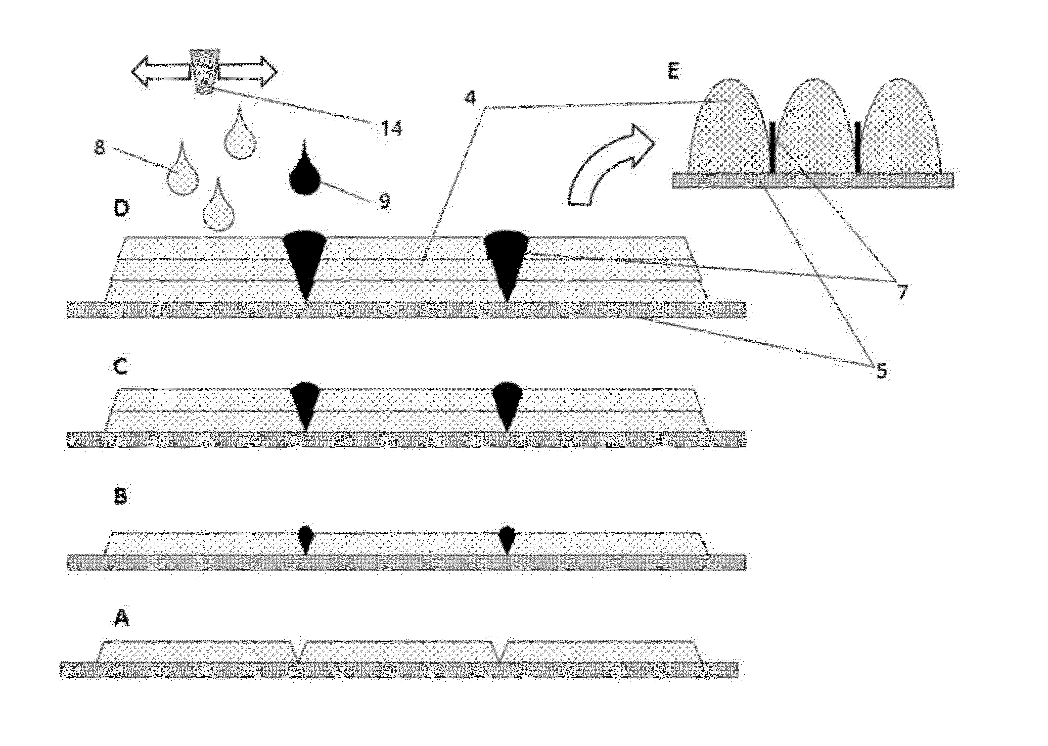
[0052]the formation of the pixelated structure of the phosphor coating deals with the two or more stage process, during which the hydrophobic coating material 22 is deposited between the areas of individual photosensitive pixels using the discrete printing method (described above), in order to divide the photosensitive area of the array photodetector 5 with hydrophobic protective strips 23 into pixel areas (FIG. 6). In this case, an active (photosensitive) areas of the pixels may be coated with a hydrophilic material (not shown in the drawings). Thereafter, the photodetector is brought into contact with the phosphor material 8 (phosphor suspension solution), for example, by means of immersing or pouring. A component of this solution (phosphor 4) is deposited only on the areas that have not been coated with the hydrophobic substance. Finally, the pixelated structure is immediately formed on the entire surface due to various effects of surface tension (such as the formation of water d...

embodiment 2

[0053]Another important feature of the method for manufacturing of detectors of penetrating radiation is, the ability to modify the properties of the scintillator across the depth of phosphor structure 21, for example, layers with one spectrum (efficiency) of luminescence can be deposited in the surface (in the direction of penetration of X-rays or gamma rays) layers of structured phosphor, and the layers with another spectrum (efficiency) of luminescence can be deposited in the deep layers (FIG. 5B). Special X-ray absorbent layers can be deposited directly on the photodetector array followed by deposition of luminescent layers.

[0054]According to embodiment 2, the variations in the form of individual structural elements of the phosphor is possible during deposition in order to optimize the luminous efficiency and minimize consumption of scintillator material in the process of deposition (FIG. 5A).

[0055]According to methods proposed according to embodiments 1 and 2, the produced “sc...


PUM


Abstract

The proposed group of inventions relates to methods for depositing fluorescent coatings on screens, by which an image is detected and/or converted, in particular, to methods of forming a structured scintillator on the surface of a photodetector intended for the detection of X-ray or gamma radiation, hereinafter referred to as the detected radiation, and to devices for obtaining an X-ray image, or an image obtained by detection of gamma radiation, particularly to devices for X-ray mammography and tomosynthesis. A method for forming a structured scintillator on the surface of a pixelated photodetector, wherein according to embodiment 1, at least one structural element is formed directly on the surface of the photodetector, the material of which is deposited by using a two-axis or a three-axis means for discrete deposition of liquid or heterogeneous substances. According to embodiment 2 of the method of forming a structured scintillator on the surface of a pixelated photodetector, at least one structural element is formed directly on the surface of the photodetector previously segmented with a hydrophobic insulating coating consistent with interpixel insensitive areas so that geometric shapes of depositing the material of the structural element are formed under the action of surface tension forces of the boundary of hydrophobic-hydrophilic areas of the photodetector surface. In addition, the group of inventions includes two embodiments of scintillation detectors. The inventions of the proposed group improve the manufacturability with simultaneous extension of the scope of application.

Description

BACKGROUND OF THE INVENTION[0001]1. Field of the Invention[0002]The proposed group of inventions relates to methods for depositing luminescent coatings on the screens, using which an image is detected and / or converted, in particular, to methods of forming a structured scintillator on the surface of a photodetector intended for detection of X-ray or gamma radiation, hereinafter referred to as the detected radiation, as well as to devices for obtaining an X-ray image or an image obtained by detection of gamma radiation, particularly to devices for X-ray mammography and tomosynthesis.[0003]2. Description of Related Art[0004]So-called “flat” visible image detectors, including those for mammography, which performs the conversion of X-ray image (“shadow”) of the test subject to the electrical signals, are used to construct digital X-ray detectors. These flat detectors are full-dimensional (array) image sensors with a spatial conversion scale of 1:1.[0005]The photodetector itself has a hig...

Claims


Application Information

Patent Timeline
IPC IPC(8): G01T1/20
CPCG01T1/2018G01T1/2012G01T1/20
Inventor SUPONNIKOV, DMITRY ALEKSANDROVICHPUTILIN, ANDREI NIKOLAEVICHDABAGOV, ANATOLIY RUDOLFOVICH
Owner STC MT
Why Eureka
Try Eureka