Readily strippable cable

a stripping and cable technology, applied in the field of electrical cables, can solve the problems of time-consuming, time-consuming, and inconvenient repair, and achieve the effects of reducing the cost of repair

Active Publication Date: 2016-06-02
JOYCE CRAIG M
View PDF8 Cites 7 Cited by
  • Summary
  • Abstract
  • Description
  • Claims
  • Application Information

AI Technical Summary

Benefits of technology

[0011]One embodiment of the present invention provides a readily-strippable cable comprising: at least two wires encapsulated by a continuous electrically insulating layer wherein each encapsulated wire is connected to an adjacent wire by a relatively thinner portion of the insulating layer, the insulating layer having at least one relatively weak portion per encapsulated wire that extends along the length of the cable and is substantially uniform in position and strength along the length of the cable; and wherein the weak portion is configured to allow the insulating layer to split along the relatively weak portion and down the length of the cable upon separation of encapsulated wires by application of force against the relatively thinner portion of insulating layer in a direction substantially perpendicular to the length of the cable, thereby exposing the wire without the use of a secondary operation.

Problems solved by technology

This process takes both time and skill and can be time consuming, even for experienced installers, especially when the time consumed is considered over the course of a project.
Errors during this operation may also result in the insulation surrounding the conductor or the wire itself being compromised or severed, requiring additional time to be spent on repair, if noticed by the installer, before the work can proceed.
In addition to time and skill requirements, this seemingly simple task also occasionally results in workplace injuries.
Cables, which contain a plurality of individually-sheathed wires, present an even larger challenge to installers and a significantly larger risk of costly and / or time consuming errors being made.
With cables, the outer sheathing must be cut away to expose the jacketing of individual wires for stripping, further increasing the time an electrician, HVAC tech, professional installer, homeowner or other person installing the wiring must spend preparing the wires for installation and the risk of damage to the underlying conductor from accidental puncture of the protective jacket during sheathing removal.
A somewhat related problem involves ductless mini-split A / C systems.
While the systems themselves are relatively easy to install, relative to traditional centralized air conditioning systems, the cabling for such systems is relatively complicated, requiring AC power wires, DC signal or communications conductors and non-current carrying ground wires to function, each of which must be separated by sheathing in addition to that of the individual wires.
There is currently no cable that can provide ease of use, durability and the required connectors for installation of such a system, while meeting code requirements.
Another problem area for electricians is thermostat wiring.
The restricted space available to the electrician in such an area increases the probability of a costly error, namely the unintentional severing of a wire or laceration injury.
These specialty cables, however, have a number of problems and even create problems in addition to those encountered when using traditional cabling.
One problem with such specialty cables is that the string is often not very effective at allowing the installer to strip the outer jacket, typically requiring significant force to be exerted by the electrician, which can result in damage to the fine wires commonly used for this application.
Another issue is that these strings must be embedded in the cable, requiring additional space and materials while increasing complexity of the manufacture; this technique cannot be used for fine wires.
Still another issue is that this string must be cut after it has served its purpose, resulting in an additional opportunity for installer error that could result in injury or accidental severing of a needed wire.

Method used


Image

  • Readily strippable cable
  • Readily strippable cable
  • Readily strippable cable

Examples


Embodiment Construction

[0063]The invention is susceptible of many embodiments and variations. What is described here is illustrative, but not limiting, of the scope of the invention.

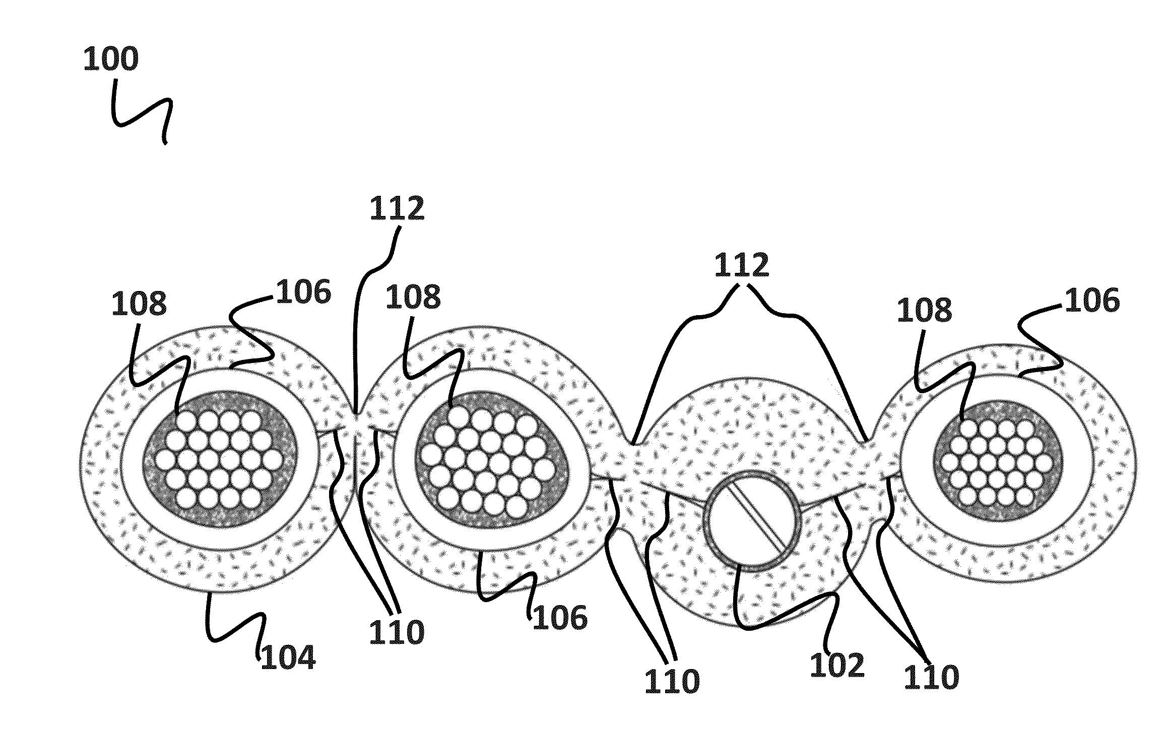
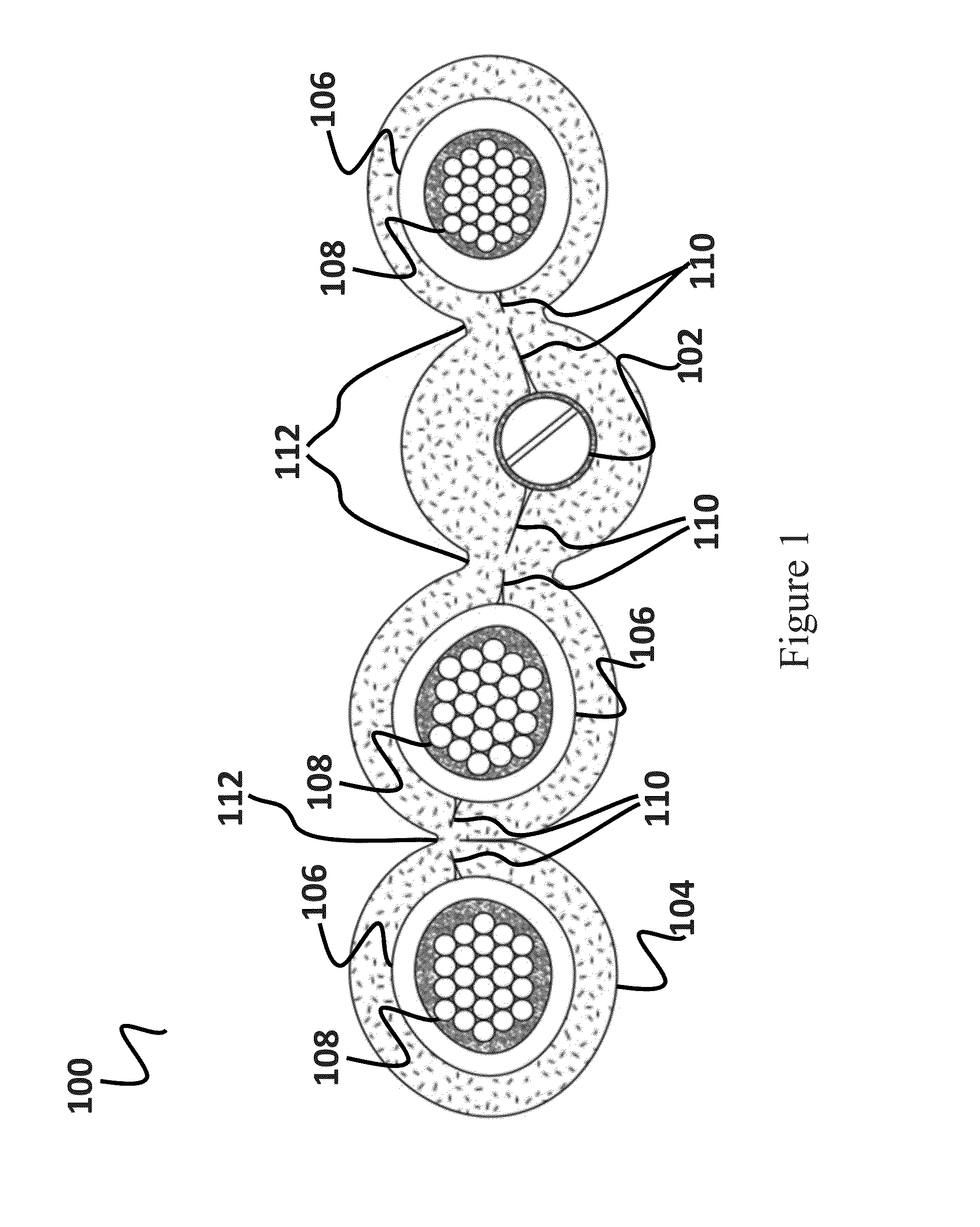
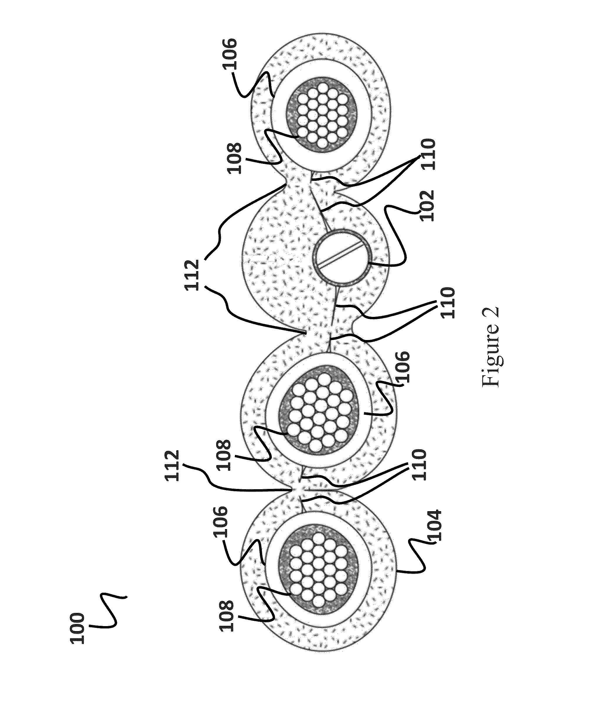
[0064]Referring to FIG. 1, a front-elevation sectional view of a four-wire cable 100 having an offset ground wire 102, or bonding conductor 102 (an insulated or uninsulated conductor forming part of the cable 100 assembly which is used for the purpose of connecting non-current carrying parts of electrical equipment to a system grounding conductor), cable sheathing 104 and wire jacketing 106 configured in accordance with one embodiment of the present invention is shown. More specifically, the cable 100 shown comprises: multiple wire cores 108, the portions of insulated wires, which may be stranded and / or solid conductors, lying under a protective covering 106, the wire jacketing 106; a cable sheath 104, the overall protective covering applied to the cable 100; a bonding conductor 102; and wire jacketing 106, which encapsulates ...


PUM

PropertyMeasurementUnit
electrically conductiveaaaaaaaaaa
lengthaaaaaaaaaa
strengthaaaaaaaaaa

Abstract

A readily-strippable cable is herein described having at least two wires encapsulated by a continuous electrically insulating layer, the insulating layer having at least one relatively weak portion that extends along the length of the cable and is substantially uniform in position and strength along the length of the cable; and wherein the weak portion is configured to allow the insulating layer to split along the relatively weak portion and down the length of the cable upon separation of the encapsulated wires by application of force against the relatively weaker portion of insulating layer in a direction substantially perpendicular to the length of the cable, thereby exposing the wires without the use of a secondary operation.

Description

RELATED APPLICATIONS[0001]This application is a continuation in part of U.S. application Ser. No. 14 / 826,483, filed Aug. 14, 2015, which is herein incorporated by reference in its entirety for all purposes. U.S. application Ser. No. 14 / 826,483 claims the benefit of U.S. Provisional Application No. 62 / 070,161, filed Aug. 18, 2014. That application is also herein incorporated by reference in its entirety for all purposes.FIELD OF THE INVENTION[0002]The invention relates to electrical cables, and more particularly, to readily strippable cables and wires particularly suited for use in ductless mini-split AC systems, thermostats and other residential and commercial wiring applications.BACKGROUND OF THE INVENTION[0003]Existing electrical wires and cable and their associated methods of installation require the use of tools, such as wire strippers and cutters, to expose the conductive elements of the wires in preparation for their connection to an electrical system. This process takes both ...

Claims


Application Information

Patent Timeline
Patent Type & Authority Applications(United States)
IPC IPC(8): H01B7/38H01B7/08H01B7/02H01B13/14H02G9/02B29C48/08B29C48/12B29C48/156B29C48/21B29C48/23
CPCH01B7/38H01B13/143H01B7/0823H01B7/0275H02G9/02B29K2101/00B29K2995/0098B29L2031/3412B29L2031/3462B29K2105/045B29K2105/046B29L2009/00H02G1/1273H02G1/1295B29C48/08B29C48/12B29C48/21B29C48/23B29C48/156B29C2793/0054
Inventor JOYCE, CRAIG M.
Owner JOYCE CRAIG M
Why Eureka
Try Eureka