Numerically controlled tower type combination drive pumping unit and tower moving system

a technology of pumping unit and combination drive, which is applied in the direction of machines/engines, positive displacement liquid engines, borehole/well accessories, etc., can solve the problems of low work efficiency and added effort, and achieve the effect of reducing the required force, saving time and labor, and reducing the friction of rolling

Active Publication Date: 2016-06-09
INT BUSINESS ALLIANCE MANAGEMENT
View PDF4 Cites 14 Cited by
  • Summary
  • Abstract
  • Description
  • Claims
  • Application Information

AI Technical Summary

Benefits of technology

[0015]In a further embodiment of the numerically controlled tower type pumping unit with combination drive, the drive system includes a small pulley, a large pulley, a speed reducer with two or fewer shafts, a safety brake system installed on the speed reducer, a small gear and a large gear. The small pulley is fastened to an output shaft of the power system. The large pulley and the small gear are fastened on ends of the speed reducer shafts. Belts connect the small pulley and the large pulley. A safety brake system cylinder is fastened on one of the two or fewer speed reducer shafts. The cylinder is wrapped around the shaft by two compression braking elements, with each braking element fastened on a separate element mounting arm. Each element mounting arm is mounted by a shaft on a safety brake system base, with the base mounted on the operation platform. The element mounting arms are connected via an electromagnetic spring compression mechanism, which is electrically connected to the control system. The control system provides the power to activate or de-activate the mechanism to permit or to stop rotation of the speed reducer shaft in different operation situations. The safety brake system ensures proper and safe operation of the Drive pumping unit.
[0022]The earlier disclosed embodiment of the numerically controlled tower type combination drive pumping unit differentiated from prior technology in that it placed the wire rope wheel shaft or the roller wheel on the rolling plane on top of the wire rope wheel support. This allowed the wire rope wheel shaft or the roller wheels to roll on the rolling plane. The limiting plates and the locating blocks were able to fasten the wire rope wheel shaft or the roller wheels to two ends of the rolling plane. It only required one to unfasten the locating blocks and push the wire rope wheel shaft or the roller wheels to roll to one end of the rolling plane to provide space for well workover. This movement could be manually achieved with operational simplicity, time and labor saving due to the smaller rolling friction resulting in smaller required force to push the roller wheels.

Problems solved by technology

The drawback of such tower pumping units is added effort and low work efficiency during oil well workover, such workover requiring that the wire rope wheel, weighing several tons as a large diameter wheel, be moved away from its working position.

Method used


Image

  • Numerically controlled tower type combination drive pumping unit and tower moving system
  • Numerically controlled tower type combination drive pumping unit and tower moving system
  • Numerically controlled tower type combination drive pumping unit and tower moving system

Examples


Embodiment Construction

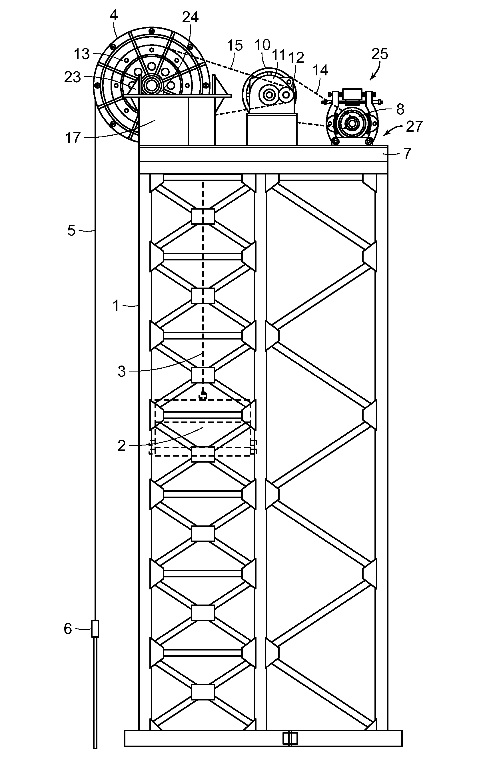
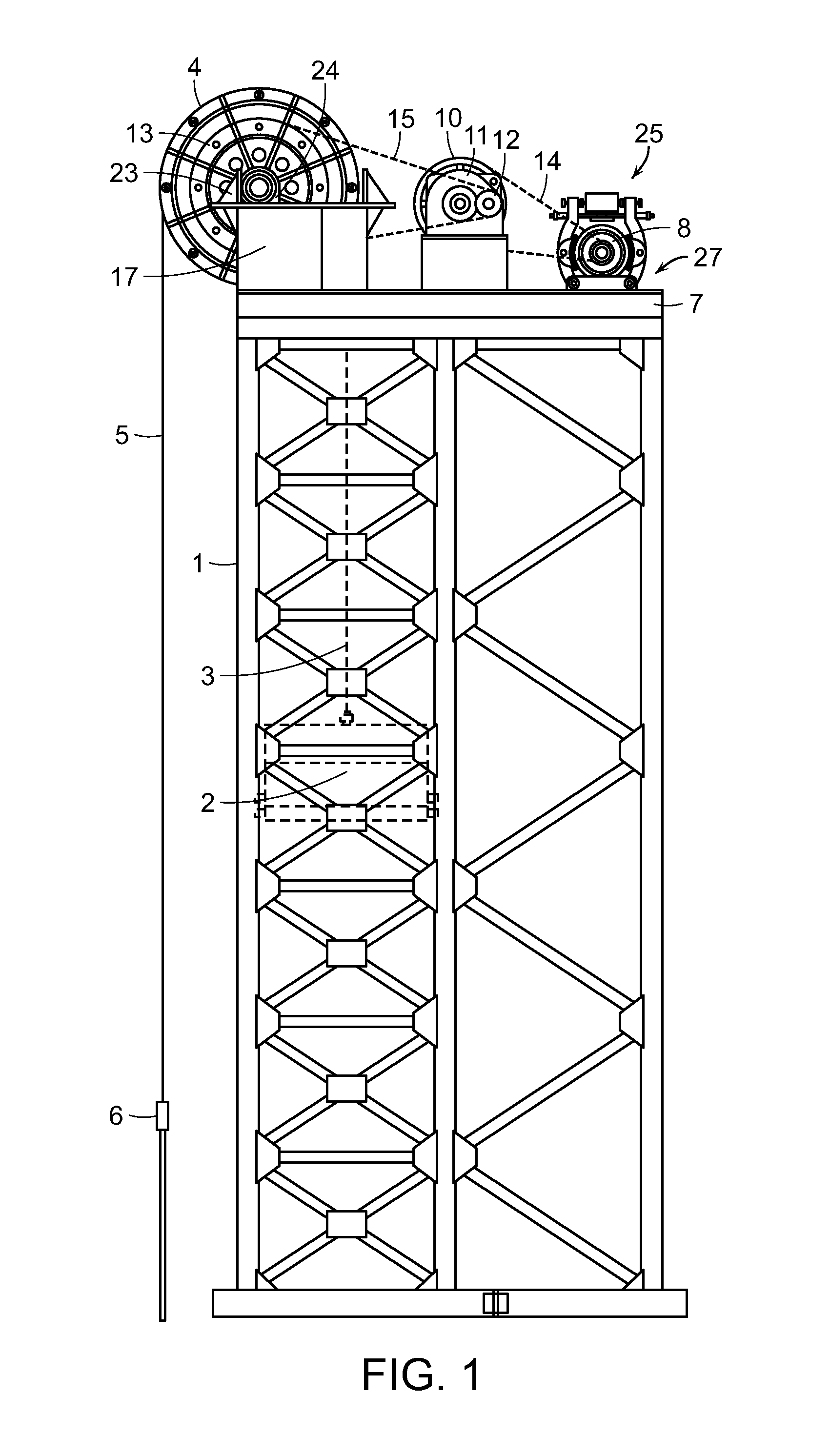
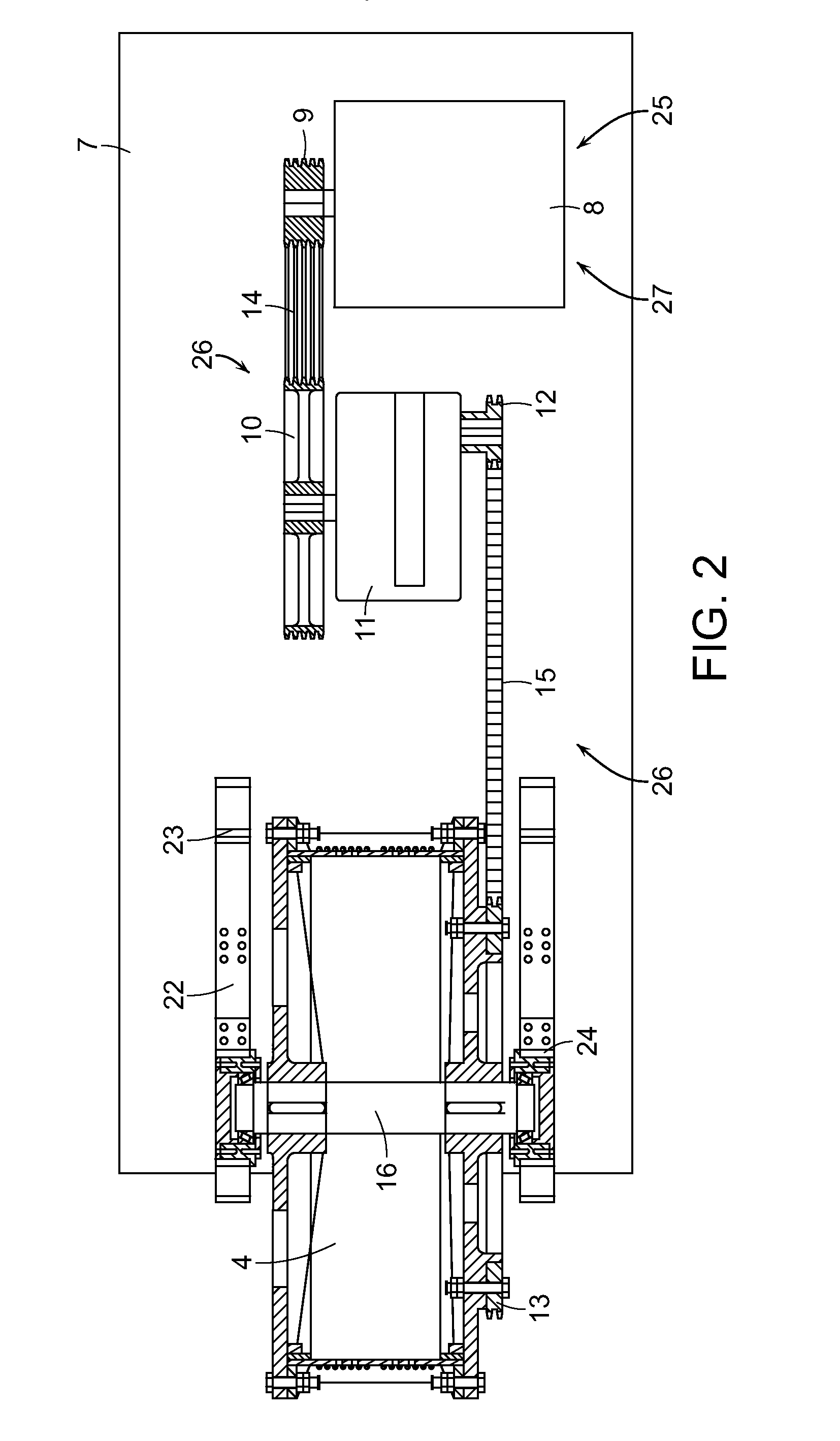
[0040]In the following detailed description, previously disclosed embodiments of the numerically controlled tower type combination drive pumping unit are shown in FIGS. 1-5. These embodiments, as described in the following paragraphs, vary in the manner in which the drive system is connected to the wire rope wheel.

[0041]As FIG. 1 and FIG. 2 indicate, the first embodiment of the prior disclosed invention of a numerically controlled tower pumping unit with combination drive includes a main tower frame 1, a power system 25, a drive system 26, a control system 27, a balance weight box 2, a balance weight pull rope 3, a wire rope wheel 4, a drive wire rope 5, and a wire rope hanger 6. The power system 25, the drive system 26, the control system 27, and the wire rope wheel 4 are all installed on an operation platform 7 at the top of the main tower frame 1. The control system 27 is electrically connected to and / or integrated with the power system 25, the power system 25 having a motor 8. T...


PUM


Abstract

A numerical controlled drive tower pumping unit includes a main tower frame, a power system, a drive system, a control system, a wire rope wheel, a balance weight box, and a suction rod. The power system, drive system, and control system work to alternately raise and lower the suction rod. The pumping unit includes a safety braking system configured to permit free rotation of the drive system in a normal operating state and prevent rotation of the drive system in an abnormal operation state. The pumping unit includes a tower moving mechanism configured to roll the main tower frame along a foundation frame from a normal operation position with the main tower frame proximate to a wellhead borehole to a workover position with the main tower frame distant from the wellhead borehole. The moving mechanism includes retractable roller assemblies to facilitate movement of the main tower frame.

Description

RELATED APPLICATIONS[0001]This is a continuation-in-part application of U.S. patent application Ser. No. 13 / 810,166, filed Jan. 14, 2013, which is a U.S. National Stage application under 35 U.S.C §371 of International Application No. PCT / CN2011 / 077098, filed Jul. 13, 2011.FIELD OF THE INVENTION[0002]The present invention is generally directed to a mechanical device or apparatus for the extraction of oil from a well. More particularly, the present invention is directed to a numerically controlled tower-type oil pumping unit having a combination drive with a safety brake system to provide for safer operation. The invention also includes a tower moving system to address problems in similar units with well workover.BACKGROUND OF THE INVENTION[0003]Currently, in oil extracting fields, beam pumping units are gradually being replaced by tower-type oil pumping units resulting from their benefits of a simpler structure, simpler operation and maintenance, low unit cost, and low energy consump...

Claims


Application Information

Patent Timeline
Patent Type & Authority Applications(United States)
IPC IPC(8): E21B19/06B66F11/00B66F17/00F04B47/02
CPCE21B19/06B66F17/00B66F11/00F04B47/02E21B43/126F04B47/022
Inventor MAO, HONGWEICHEN, DAH KONG
Owner INT BUSINESS ALLIANCE MANAGEMENT
Why Eureka
Try Eureka