Floor mounted racking arm for handling drill pipe

a drilling pipe and floor-mounted technology, which is applied in the direction of drilling pipes, transportation and packaging, drilling rods, etc., can solve the problems of large diameter drill pipes, limited space available for drilling pipe storage, long and heavy drill pipe stands, etc., and achieves manual guidance and control of the lowermost pin end of the drill pipe stand between the wellcenter and the setback. cumbersome and difficul

Active Publication Date: 2016-06-09
NAT OILWELL VARCO LP
View PDF4 Cites 42 Cited by
  • Summary
  • Abstract
  • Description
  • Claims
  • Application Information

AI Technical Summary

Benefits of technology

[0022]The following presents a simplified summary of the present disclosure in order to provide a basic understanding of some aspects disclosed herein. This summary is not an exhaustive overview of the disclosure, nor is it intended to identify key or critical elements of the subject matter disclosed here. Its sole purpose is to present some concepts in a simplified form as a prelude to the more detailed description that is discussed later.

Problems solved by technology

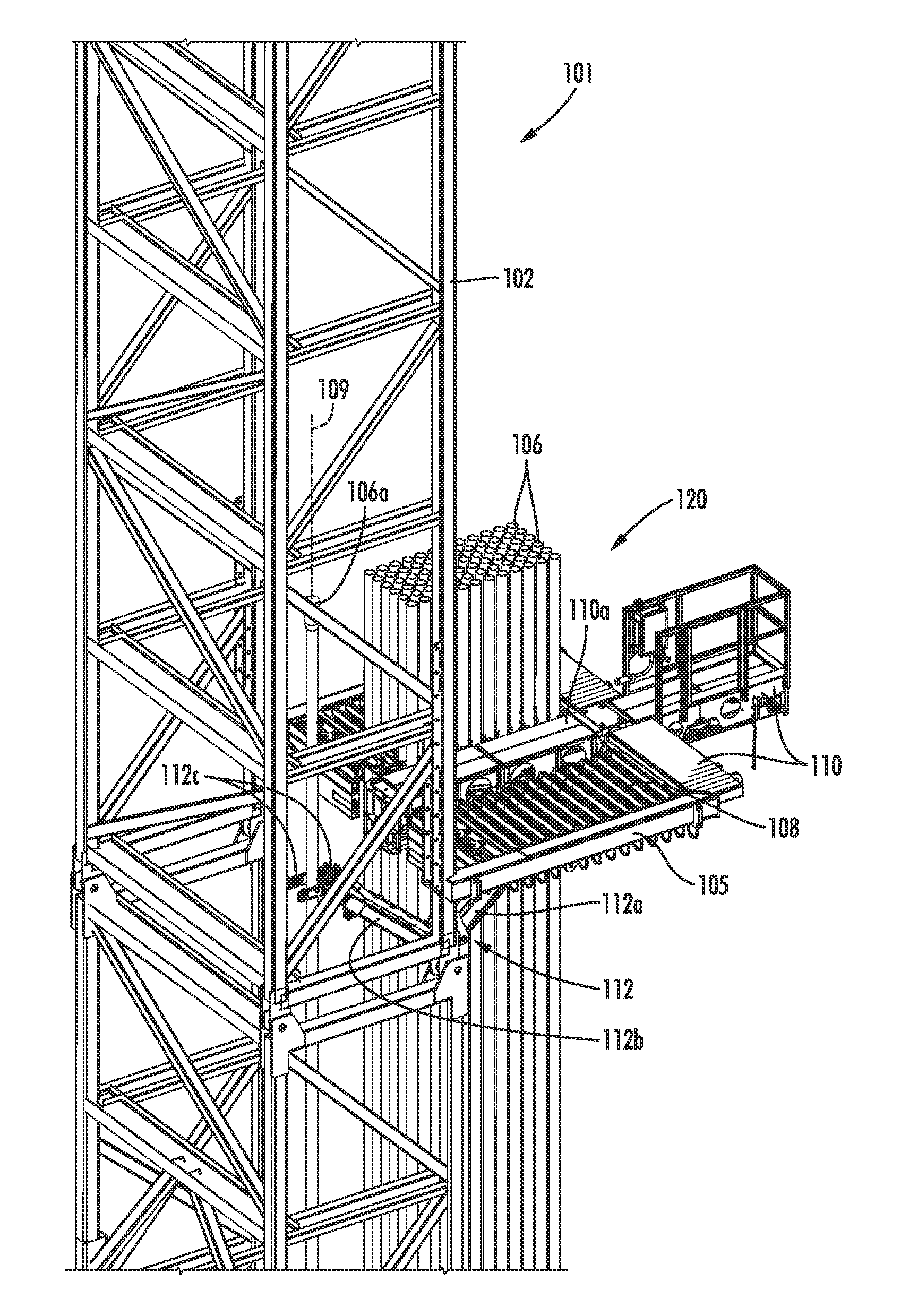
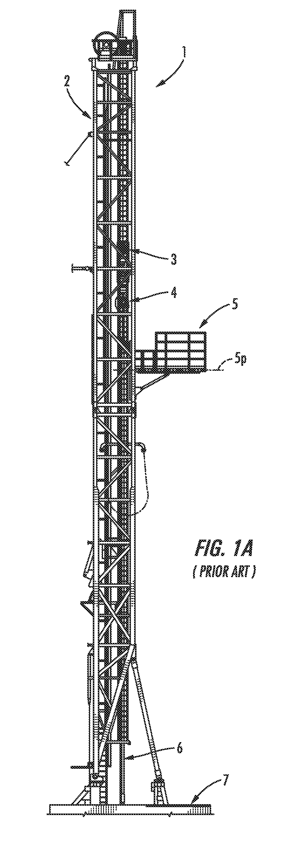
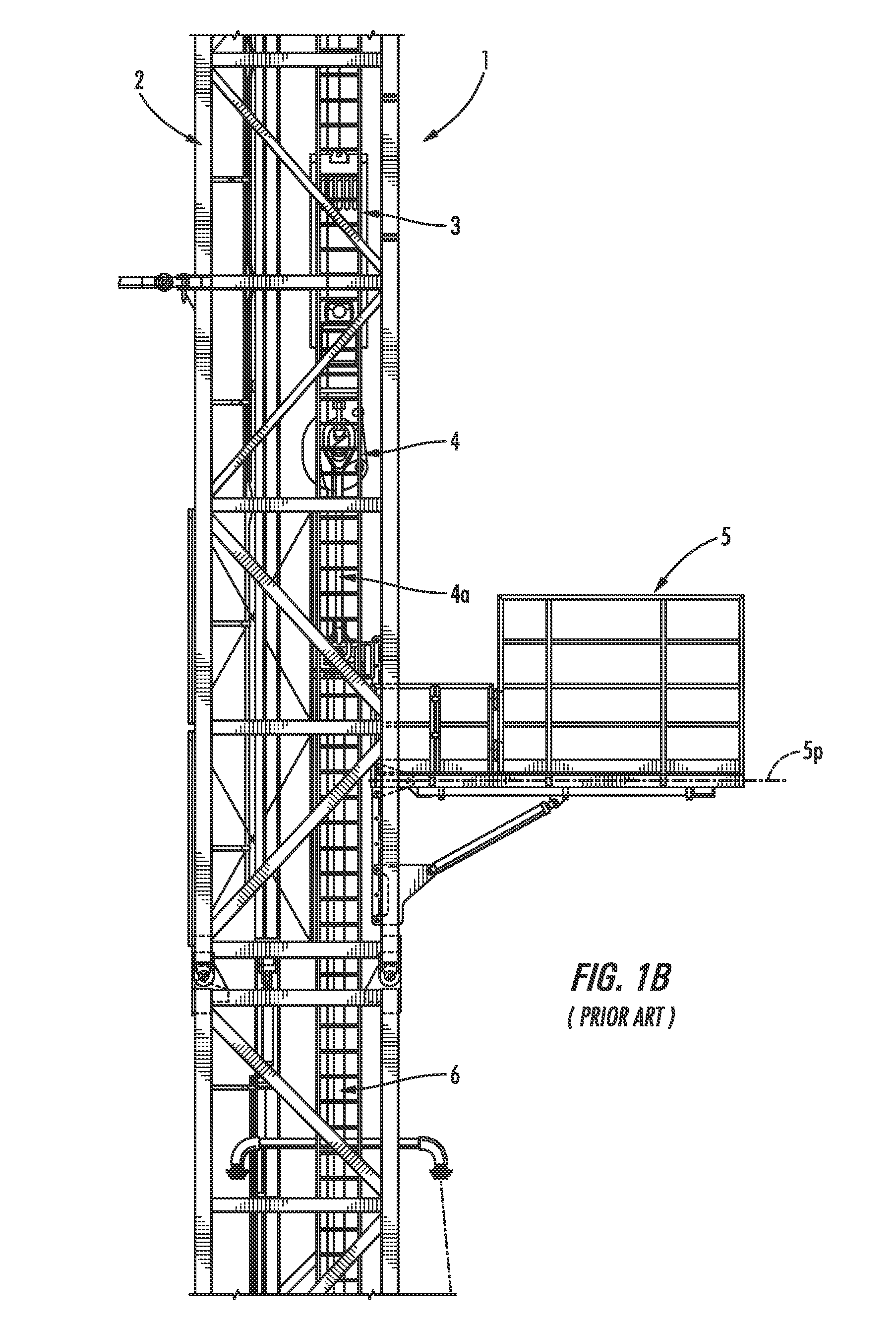
Due to the relatively compact footprint that may be associated with drilling mast structures, there may be very limited space available for storing the drill pipe and other tubular members adjacent to the drilling mast 2.
However, it is generally well understood that such guidance and movement of large sections of drill pipe may involve a variety of handling difficulties, particularly as drilling rigs have become larger and wellbore depths have become greater—factors which can often lead to larger diameter drill pipe, and longer and heavier drill pipe stands.
In such cases, manual guidance and control of the lowermost pin end of the drill pipe stand between the wellcenter and the setback can be cumbersome and difficult, due to the momentum of the swaying drill pipe stand.
This can be problematic in some applications, particularly for operations performed with portable land-based (onshore) rigs, where drill floor space is at a premium.

Method used


Image

  • Floor mounted racking arm for handling drill pipe
  • Floor mounted racking arm for handling drill pipe
  • Floor mounted racking arm for handling drill pipe

Examples


Embodiment Construction

[0049]Various illustrative embodiments of the present subject matter are described below. In the interest of clarity, not all features of an actual implementation are described in this specification. It will of course be appreciated that in the development of any such actual embodiment, numerous implementation-specific decisions must be made to achieve the developers' specific goals, such as compliance with system-related and business-related constraints, which will vary from one implementation to another. Moreover, it will be appreciated that such a development effort might be complex and time-consuming, but would nevertheless be a routine undertaking for those of ordinary skill in the art having the benefit of this disclosure.

[0050]The present subject matter will now be described with reference to the attached figures. Various systems, structures and devices are schematically depicted in the drawings for purposes of explanation only and so as to not obscure the present disclosure ...


PUM


Abstract

A racking arm assembly is adapted to be mounted on a drill floor of a drilling rig and includes a lift arm assembly having a first arm that is movably coupled to a vertical support column, wherein the lift arm assembly is adapted to be raised and lowered along a vertical length of the vertical support column during a pipe handling operation. A lift jaw assembly is pivotably coupled to a second arm of the lift arm assembly and includes a lift jaw assembly having a lift jaw gripping apparatus that is adapted to grip and fixedly hold a drill pipe stand proximate a pin end of the drill pipe stand during the pipe handling operation. The lift jaw gripping apparatus is further adapted to be rotated relative to the lift arm assembly about a substantially horizontal axis while the lift jaw gripping apparatus is fixedly holding the drill pipe stand.

Description

BACKGROUND[0001]1. Field of the Disclosure[0002]The present disclosure is generally directed to methods and apparatuses for handling drill pipe and other tubular members during drilling and / or workover operations of a well, and in particular to a drill floor mounted racking arm for lifting and positioning drill pipe stands.[0003]2. Description of the Related Art[0004]Drilling masts are vertical structures that are commonly used to support a drill string while a well is being drilled. Drilling masts usually have a relatively compact, rectangular footprint, as opposed to a derrick structure, which typically has a steep pyramidal shape. The rectangular shape of the typical drilling mast also offers relatively good overall stiffness, which allows the mast to be lowered to a horizontal position. The compact, rectangular shape of the drilling mast structure therefore facilitates transportation of the drilling rig over surface roads, many times without the need for obtaining special shippi...

Claims


Application Information

Patent Timeline
Patent Type & Authority Applications(United States)
IPC IPC(8): E21B19/14E21B19/24
CPCE21B19/24E21B19/14
Inventor KEOGH, GREGORYZAHN, BALDWINYELDELL, CHRISTOPHERKOETHER, ALBERT
Owner NAT OILWELL VARCO LP
Why Eureka
Try Eureka