Solid electrolyte fuel cell

a fuel cell and solid electrolyte technology, applied in the direction of solid electrolyte fuel cells, fuel cells, collectors/separators, etc., can solve the problems of reducing the initial cell performance, and thus reducing the cell performance, so as to achieve the effect of reducing the lifetime or reliability of the cell

Active Publication Date: 2016-06-09
MURATA MFG CO LTD
View PDF9 Cites 0 Cited by
  • Summary
  • Abstract
  • Description
  • Claims
  • Application Information

AI Technical Summary

Benefits of technology

[0007]In the case of the connection body for a solid oxide fuel cell, which is disclosed in Patent Document 1, when the material of the anode contains a single nickel metal, the PLANSEE or silver-palladium alloy listed as a material for the anode contact reacts with the single nickel metal. This reaction gradually proceeds over time. For this reason, the electrical connections are deteriorated over time, the cell performance is thus decreased over time, and as a result, the lifetime or reliability of the cell is decreased.

Problems solved by technology

For this reason, the electrical connections are deteriorated over time, the cell performance is thus decreased over time, and as a result, the lifetime or reliability of the cell is decreased.
Thus, the electrical resistance of the cathode is increased, thus decreasing the initial cell performance.

Method used


Image

  • Solid electrolyte fuel cell
  • Solid electrolyte fuel cell
  • Solid electrolyte fuel cell

Examples


examples

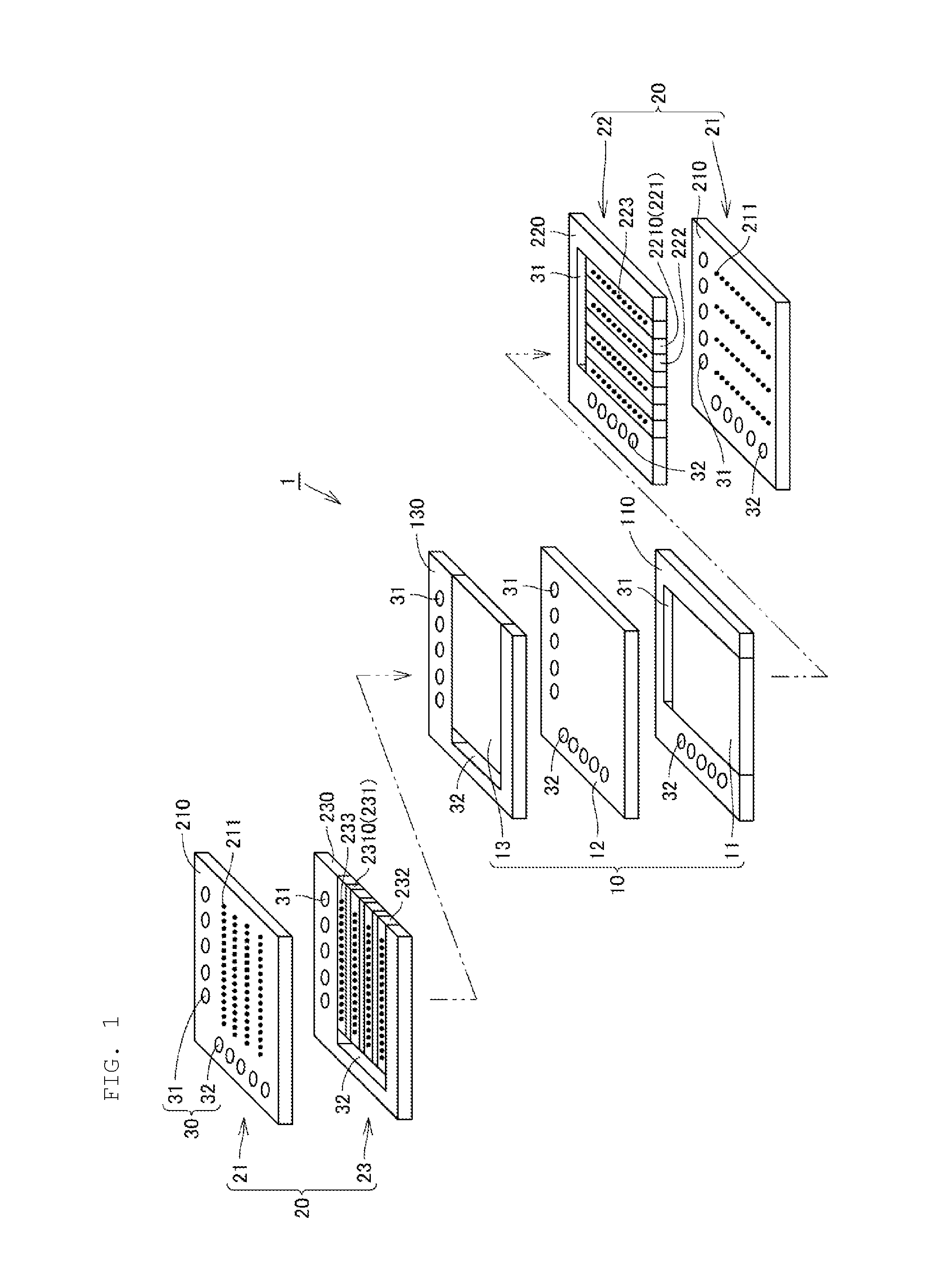
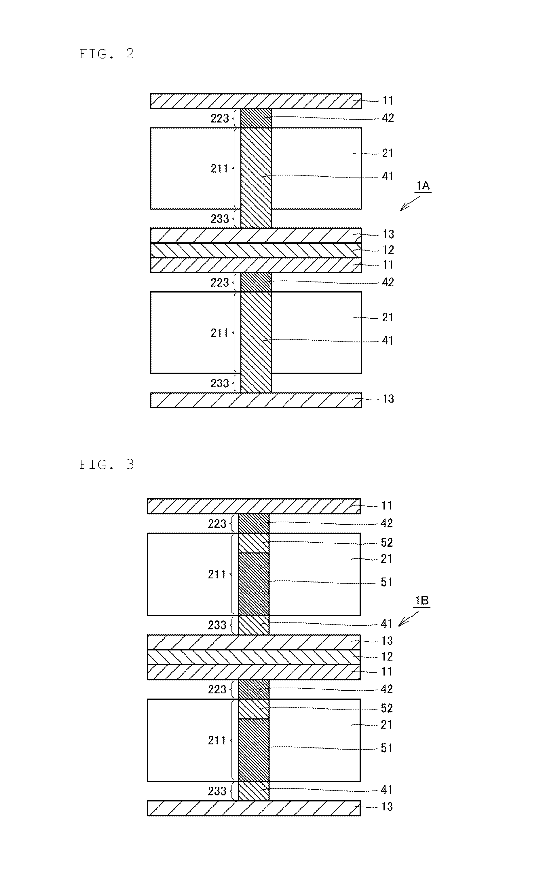
[0054]Hereinafter, Examples 1 to 8 with the anode contact layer and cathode contact layer according to the present invention in FIG. 2 or 3 will be described as examples of preparing solid electrolyte fuel cells according to the present invention in accordance with the embodiment described above, and Comparative Examples 1 to 3 of preparing solid electrolyte fuel cells without the anode contact layer and / or the cathode contact layer according to the present invention will be described for comparison with the electrical connection structure of the present invention.

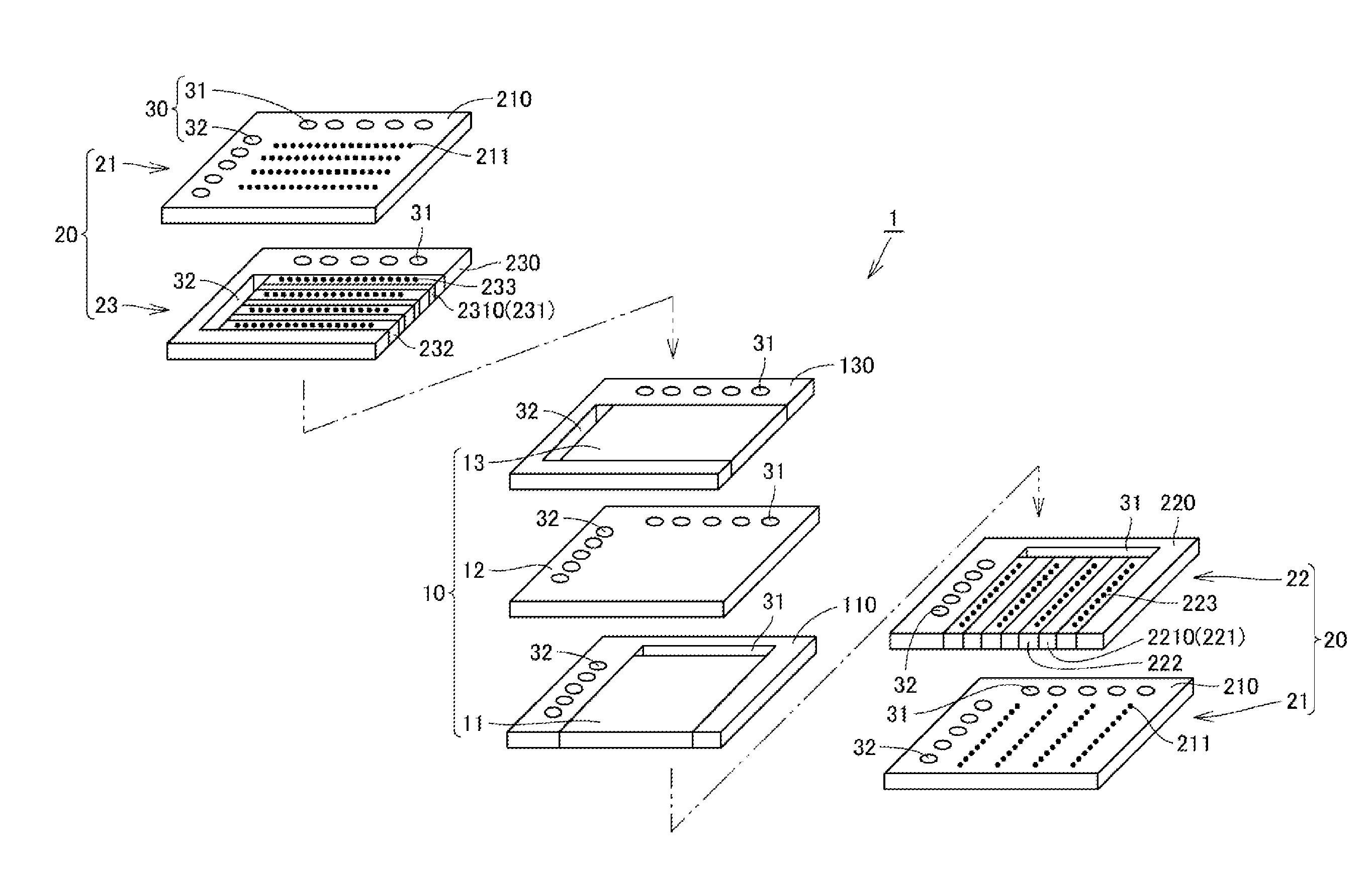
[0055]Fist, material powders for members (A) to (H) constituting a unit module of a solid electrolyte fuel cell according to the embodiment shown in FIG. 1 were prepared as follows.

[0056](A) Fuel electrode layer 11: Mixture (Ni—ScCeSZ) of 60 weight % nickel (Ni) and 40 weight % zirconia (ZrO2) stabilized with 10 mol % (additive amount) of scandia (Sc2O3) and 1 mol % (additive amount) of ceria (CeO2) (scandia-ceria stabiliz...


PUM

PropertyMeasurementUnit
diameteraaaaaaaaaa
diameteraaaaaaaaaa
lengthaaaaaaaaaa

Abstract

A solid electrolyte fuel cell that includes a fuel electrode contact layer in contact with a fuel electrode layer and an air electrode contact layer in contact with an air electrode layer. The fuel electrode layer includes a first single metal or a first alloy, the fuel electrode contact layer includes a first conductive oxide, the air electrode layer includes a second conductive oxide, and the air electrode contact layer includes a second single metal or a second alloy.

Description

CROSS REFERENCE TO RELATED APPLICATIONS[0001]The present application is a continuation of International application No. PCT / JP2014 / 069059, filed Jul. 17, 2014, which claims priority to Japanese Patent Application No. 2013-171950, filed Aug. 22, 2013, the entire contents of each of which are incorporated herein by reference.FIELD OF THE INVENTION[0002]The present invention generally relates to a solid electrolyte fuel cell, and more particularly, to a solid electrolyte fuel cell including contact layer respectively in contact with an anode layer and a cathode layer for extracting electric power generated in each power generation element section (cell) of the fuel cell, and for mutually and electrically connecting a plurality of cells.BACKGROUND OF THE INVENTION[0003]In general, a flat-plate solid electrolyte fuel cell (also referred to as solid oxide fuel cell (SOFC)) is composed of: a plurality of plate cells each as a power generation element composed of an anode (negative electrod...

Claims


Application Information

Patent Timeline
Patent Type & Authority Applications(United States)
IPC IPC(8): H01M8/0217H01M8/0206
CPCH01M8/0217H01M2008/1293H01M8/0206H01M8/0208H01M8/0215H01M8/0256Y02E60/50
Inventor TAKATA, KAZUHIDE
Owner MURATA MFG CO LTD
Why Eureka
Try Eureka