Wireless power charging system

a charging system and wireless technology, applied in the direction of exchanging data chargers, transportation and packaging, sustainable buildings, etc., can solve the problems of reducing the service life of batteries, affecting the service life so as to reduce the loss of electric power, maximize charging efficiency, and save the total charging time of wireless power receiving devices.

Active Publication Date: 2016-06-09
INTEL CORP
View PDF3 Cites 4 Cited by
  • Summary
  • Abstract
  • Description
  • Claims
  • Application Information

AI Technical Summary

Benefits of technology

[0010]To solve the above-mentioned problems, the present invention is directed to a wireless power charging system formed to charge a plurality of wireless power receiving apparatuses placed in a short distance from a wireless power transmission apparatus, wherein the total charging time for a plurality of wireless power receiving apparatuses will be saved.
[0011]Moreover, when a plurality of wireless power receiving apparatuses are fully charged, the wireless power transmission system will be automatically changed to a standby mode, wherein the initial pulse signal is sending out. By doing so, the charging efficiency will be maximized while the loss of the electricity will be minimized.
[0017]The present invention formed with the above-mentioned figures is constructed to charge a plurality of wireless power receiving apparatuses located in a short distance from the wireless power transmission apparatus, wherein the advantageous effect is that the total charging time for a plurality of wireless power receiving apparatuses can be saved.
[0018]Moreover, when a plurality of wireless power receiving apparatuses are fully charged, the wireless power transmission system will be changed to a stand-y mode where the initial pulse signal is sending out. By doing so, the charging efficiency will be maximized while the loss of electric power will be minimized.

Problems solved by technology

However, when the charger and the batteries are connected or disconnected to replenish the electric power of the batteries with this connector supply system, an instant discharge may happen because of the potential differences between the charger connector and the battery connector.
Hence the foreign substances will be gradually gathered on both connectors and finally there may be a fire disaster.
Further, the collected humidity thereon will cause the discharge of the battery and other problems will be involved like the declining battery life, the low battery quality, and so on.
The conventional non-contacting charging systems with the prior art can only be used to supply the electricity to the portable devices.
There are limited practical uses because they cannot be used in various alternatives.
Besides, if a metal is placed inside the effective radius of the generated magnetic field of the primary coil, there would be a lot loss of the electricity in the primary coil and non-contacting charging system may be damaged.

Method used


Image

  • Wireless power charging system
  • Wireless power charging system
  • Wireless power charging system

Examples


Embodiment Construction

[0024]The invention will now be described in detail with reference to the accompanying drawings.

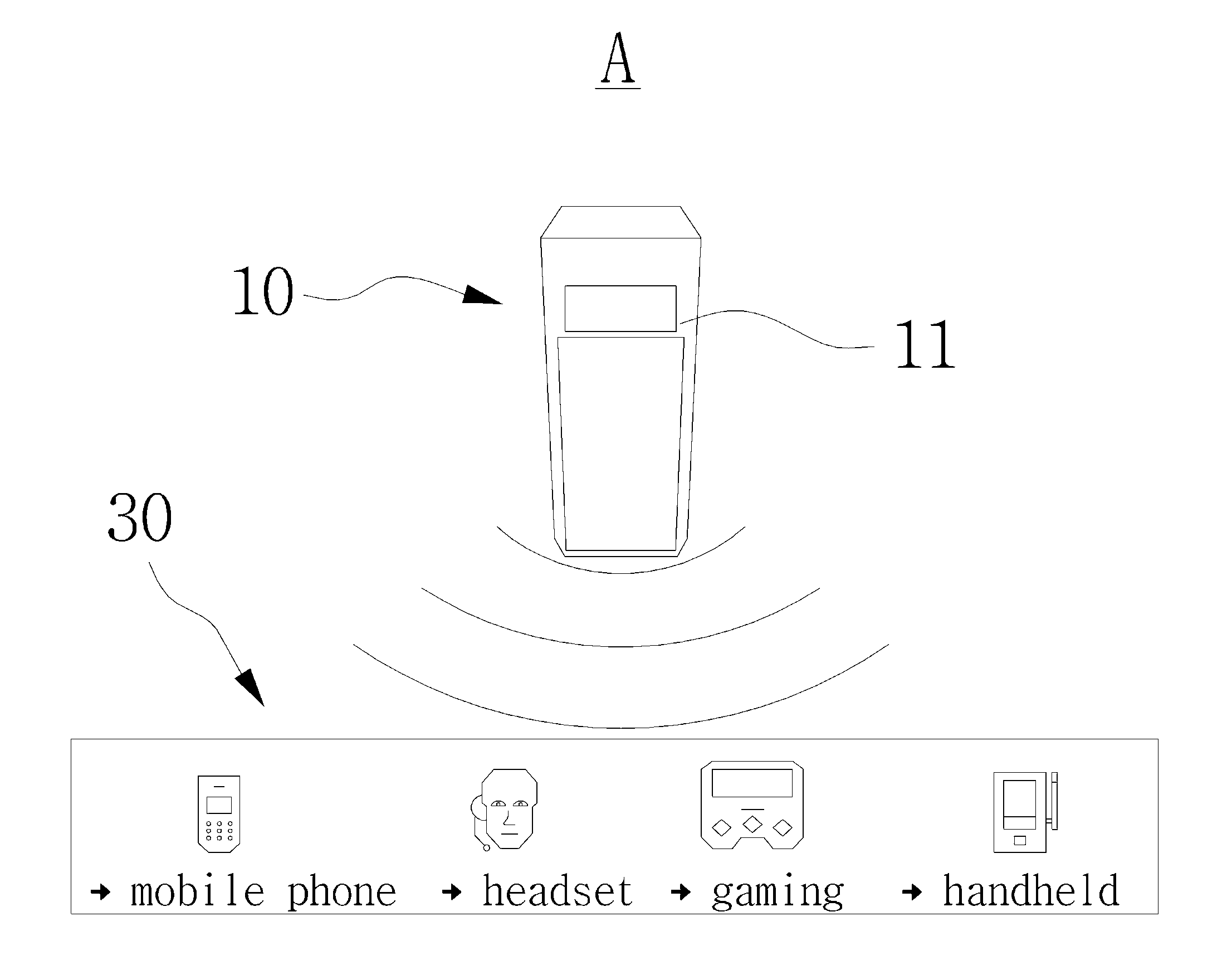
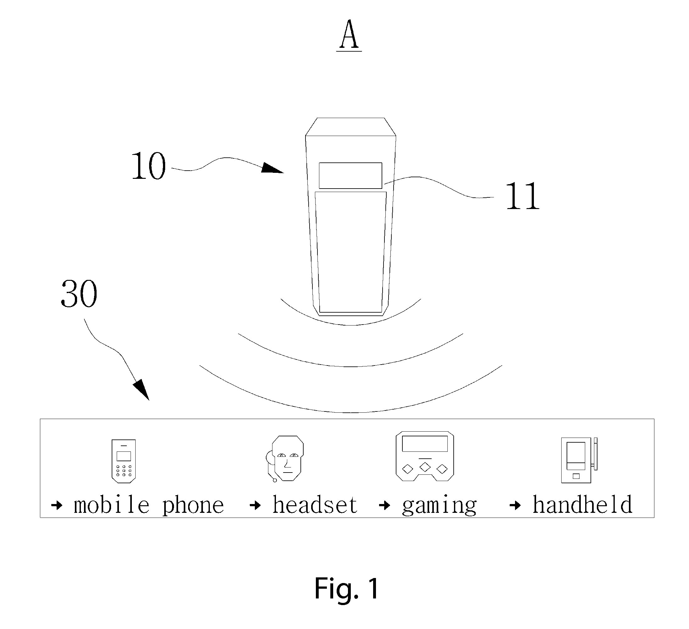
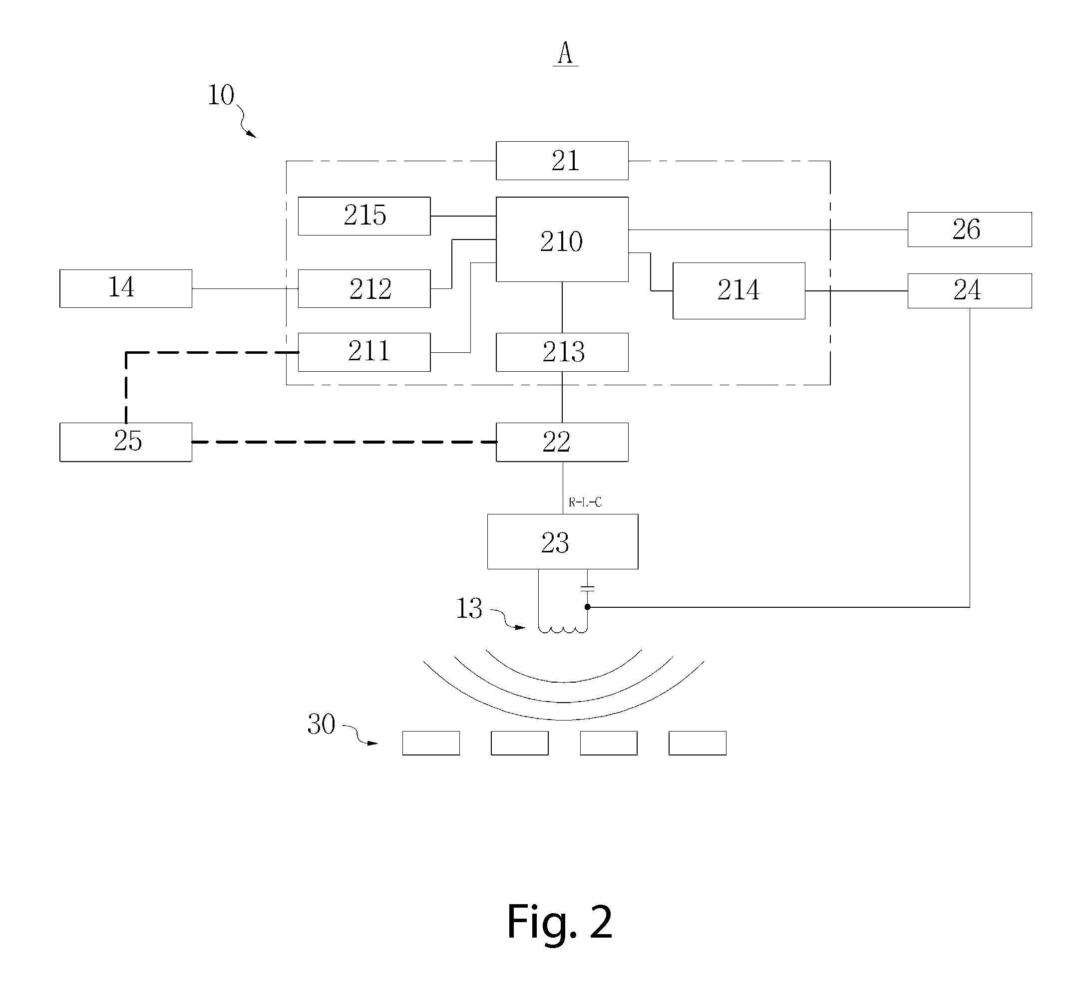
[0025]FIG. 1 is a schematic configuration view of a wireless power charging system in accordance with the present invention, FIG. 2 is a block diagram of a wireless power transmission apparatus in accordance with the present invention, FIG. 3 is a block diagram of a wireless power receiving apparatus according to the present invention, and FIG. 4 is a flow diagram of a conceptual transmission control process for the wireless power charging system in accordance with the present invention.

[0026]Referring to FIGS. 1 to 4, a wireless power charging system A is formed with a wireless power transmission apparatus 10 to transmit the power signal for charging one or a plurality of wireless power receiving apparatuses 30 located in a short distance from the wireless power transmission apparatus 10.

[0027]The wireless power transmission apparatus 10 includes a power transmission apparatus case 11 as...


PUM


Abstract

A wireless power charging system has a wireless power transmission apparatus formed to charge a plurality of wireless power receiving apparatuses located in a short distance therefrom, wherein the total charging time for the wireless power receiving apparatuses is saved. The wireless power transmission apparatus has a main control unit and a resonant converter unit, which transmit the electric signal to the wireless power receiving apparatus via the resonance signal generated from a primary charge core in order to charge the wireless power receiving apparatuses. The wireless power transmission apparatus also includes an output signal conversion module for transmitting a converted electric signal to the resonant converter unit and a received signal process module for processing a signal transmitted from the wireless power receiving apparatus.

Description

CLAIM OF PRIORITY[0001]This application claims the benefit of Korean Patent Application No. 10-2007-0123750 filed on Nov. 30, 2007, in the Korean Intellectual Property Office, the disclosure of which is incorporated herein by reference.BACKGROUND OF THE INVENTION[0002]1. Field of the Invention[0003]The present invention relates to a wireless power charging system, and more particularly, to a short-distance wireless power charging system, which has a wireless power transmission apparatus formed to charge a plurality of wireless power receiving apparatuses located in a short distance therefrom, wherein the total charging time for a plurality of wireless power receiving apparatuses can be saved.[0004]2. Description of the Related Art[0005]Portable electronic devices, such as cellular phones, personal digital assistants (PDAs), portable media players (PMPs), digital multimedia broadcasting terminal (DMB terminals), MPEG audio layer 3 (MP3) players or notebook computers, cannot be plugge...

Claims


Application Information

Patent Timeline
Patent Type & Authority Applications(United States)
IPC IPC(8): H02J7/02H02J7/04H02J7/00
CPCH02J7/04H02J7/025H02J50/80H02J50/12H04B5/0037H02J7/00045H02J7/00034H02J7/0048H02J7/00712H02J50/40H02J50/005H02J7/0045Y02B40/00
Inventor JUNG, CHUN-KIL
Owner INTEL CORP
Why Eureka
Try Eureka