Method for monitoring an oxidation catalysis device

a technology of oxidation catalysis and monitoring device, which is applied in the direction of electrical control, exhaust treatment electric control, separation process, etc., can solve the problems of spreading of temperature estimates themselves, and achieve the effect of increasing the flow rate of exhaust gas, relatively small margin of error, and easy comparison with a view to diagnosing

Active Publication Date: 2016-06-16
VITESCO TECH GERMANY GMBH
View PDF3 Cites 8 Cited by
  • Summary
  • Abstract
  • Description
  • Claims
  • Application Information

AI Technical Summary

Benefits of technology

[0022]The method according to the invention proposes monitoring a decrease in the temperature as an exothermal reaction progresses following a plurality of injections of fuel in respective stages, and therefore monitoring an operating point by comparing it against an operating point derived from a test conducted on a similar but aged oxidation catalysis device. As a result, the margin of error is relatively small, the reference having been taken from an experimental reality rather than a model, and comparison with a view to diagnosing becomes easy. When the temperature of the cumulative exothermal reaction decreases that means that the catalysis device being monitored and tested is no longer capable of converting the corresponding injected quantity of fuel, and all that is then required is for this quantity of fuel to be compared against the quantity that brings about a decrease in temperature in a catalysis device that is similar but that has been aged in a controlled way, so as for example to find itself at an acceptable limit of degradation, which still has to be defined by simple tests according to need, for example according to compliance with given legislation, in order to be able to diagnose whether or not the device being monitored and tested can still be considered to be operational. What is meant by a similar oxidation catalysis device here is a catalysis device of the same model and having the same characteristics at the outset as the one that is being monitored and tested, namely when new prior to any use. The inlet temperature of the catalysis device being monitored can be determined in the known way by modeling or by measurement using a temperature sensor. Provided the inlet temperature of the catalysis device is conformed to, the method according to the invention can be executed with the engine operating with a stable exhaust flow rate or in any engine operating mode, using a model of the outlet temperature of the catalysis device. The two solutions can be used together. A model of the outlet temperature of the catalysis device will make it possible to differentiate a phenomenon whereby the outlet temperature of the catalysis device decreases as a result of the vehicle accelerating leading to an increase in exhaust gas flow rate from a phenomenon whereby the outlet temperature of the catalysis device decreases as a result of the method according to the invention, using a simple difference from the measured temperature at the outlet of the catalysis device. Such a model of the outlet temperature of the catalysis device is known from an engine control unit and can be based on a flowmeter measuring the inlet flow rate of gases into the engine, a torque demand indicator or the fuel injection system. The stability of the exhaust gas flow rate is moreover monitored and known in an internal combustion engine by the engine control unit.
[0025]This feature allows the owner of the vehicle or the user thereof to be supplied with information relating to the imminence, as appropriate, of necessary maintenance to the vehicle DOC system, and gives him time for work to be done on the oxidation catalysis system of the vehicle.
[0027]This feature makes it possible to define a precision or resolution of the monitoring method according to the invention which corresponds to said basic divided quantity of the test quantity.

Problems solved by technology

Such a method has the chief disadvantage that its efficiency is dependent on the accuracy of the model and on the spread of the parameters used in the model, notably the quantity of fuel injected, the flow rate of the gases, the catalyst, leading to a spread in the temperature estimates themselves.

Method used


Image

  • Method for monitoring an oxidation catalysis device
  • Method for monitoring an oxidation catalysis device

Examples


Embodiment Construction

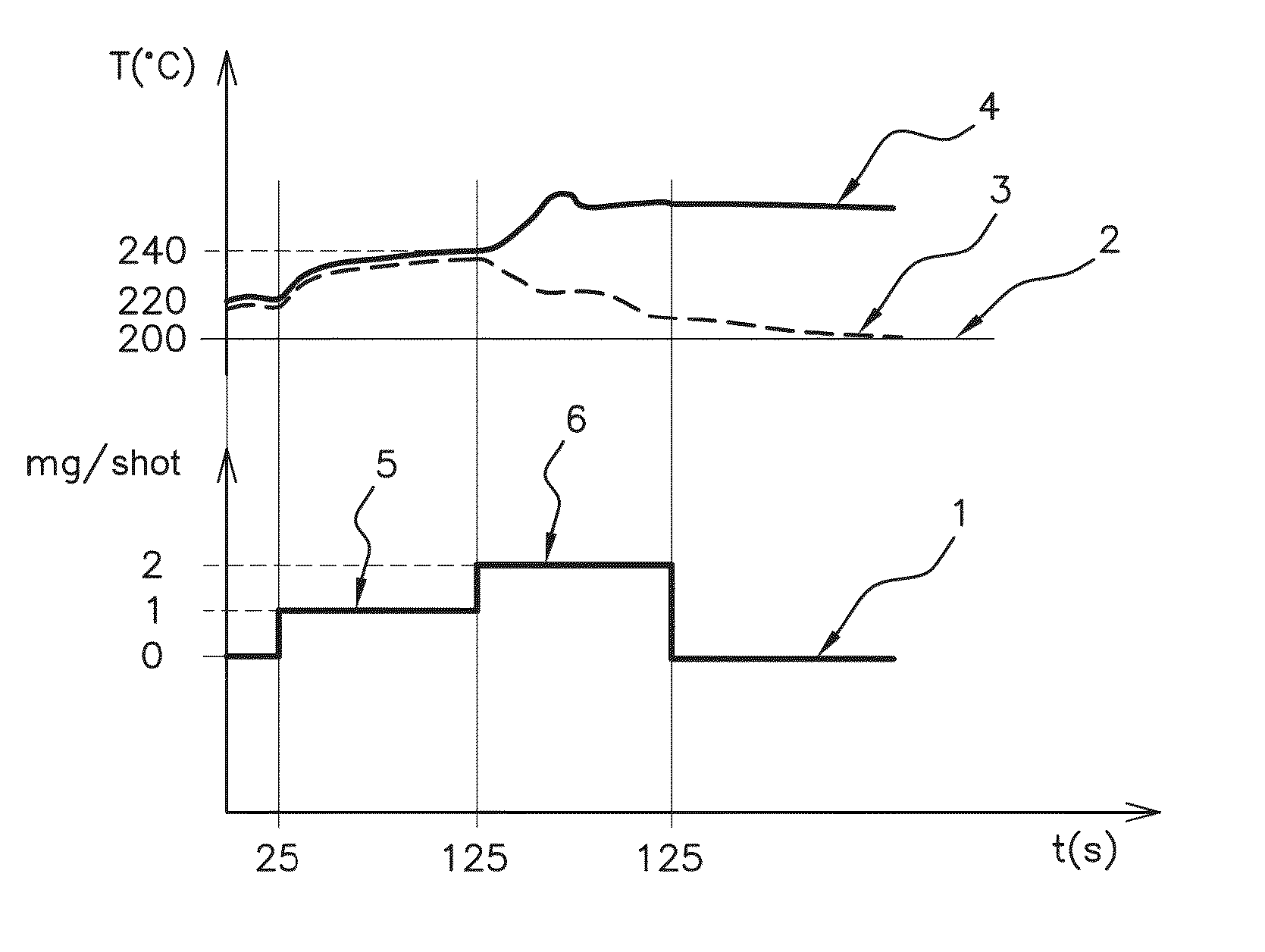
[0042]The method illustrated in FIG. 1 is a method for monitoring according to the invention, applied to an oxidation catalysis device of known type arranged also in the known way in an exhaust line of an internal combustion engine of a vehicle, for example a turbocharged diesel engine comprising, from upstream to downstream starting from the engine: the turbine of the turbocharger, the oxidation catalysis device or DOC, a particulate filter or DPF (diesel particulate filter) and a selective catalytic reduction or SCR device, or with the order of the last two swapped over. In the absence of a turbo, the oxidation catalysis device or DOC is advantageously positioned directly downstream of the engine.

[0043]FIG. 1 shows how parameters indicative of the method of monitoring according to the invention evolve. The abscissa axis represents the time t in seconds, and the ordinate axis represents three scales of parameters, namely the inlet temperature of the oxidation catalysis device or DO...


PUM


Abstract

A method for monitoring an oxidation catalysis device or DOC arranged in an exhaust line of an internal combustion engine of a vehicle, in a predetermined range of inlet (2) and outlet (3) temperatures of the DOC, includes injecting predetermined successive quantities of fuel in stages (5, 6) into the inlet of the DOC, recording the outlet (3) temperature of the DOC after each injected quantity of fuel, recording the total quantity injected for a given stage, for which the outlet temperature (3) of the DOC begins to decrease, determining a characterization of the DOC monitored, then comparing this characterization with a test characterization of a similar DOC which has been established beforehand in order to determine a threshold degradation of the DOC monitored that is not to be exceeded.

Description

FIELD OF THE INVENTION[0001]The present invention relates to a method for monitoring an oxidation catalysis device arranged in an exhaust line of an internal combustion engine of a vehicle, said method being activated while the internal combustion engine is in operation.BACKGROUND OF THE INVENTION[0002]An oxidation catalysis device, also referred to as a DOC device or DOC, standing for “diesel oxidation catalyst”, is a device placed in the exhaust line of a diesel-engined vehicle, as far as possible as close as possible to the engine so that it reaches its operating temperature of between 150° C. and 200° C. as quickly as possible, and which uses the oxygen of several of the components of the exhaust gas to perform oxidation, notably via the following three oxidation reactions:[0003]oxidation of carbon monoxide (CO),[0004]oxidation of hydrocarbons (HC),[0005]oxidation of an organic fraction of the diesel particulates (SOF).[0006]An oxidation catalysis device in an exhaust line gener...

Claims


Application Information

Patent Timeline
Patent Type & Authority Applications(United States)
IPC IPC(8): F01N11/00F01N3/10F01N13/00B01D53/94
CPCF01N11/002B01D53/944F01N2560/06F01N13/008F01N3/103F01N3/36F02D41/0235F02D41/30F01N2550/05F01N2550/02F01N2610/03F01N2900/1404F01N3/101F02D41/025F02D41/405F01N3/035F01N2430/085F01N2900/0412F01N2900/0416F01N2900/08Y02A50/20Y02T10/12Y02T10/40
Inventor MAERTENS, STEVENHEMBERT, BRICE
Owner VITESCO TECH GERMANY GMBH
Why Eureka
Try Eureka