Methods and system for compensating compressor recirculation sludge

a compressor and recirculation sludge technology, applied in the direction of electrical control, process and machine control, instruments, etc., can solve the problems of less so as to increase the effect of increasing the output power and increasing the amount of air flowing through the engin

Active Publication Date: 2016-06-16
FORD GLOBAL TECH LLC
View PDF0 Cites 8 Cited by
  • Summary
  • Abstract
  • Description
  • Claims
  • Application Information

AI Technical Summary

Benefits of technology

[0002]A supercharged or turbocharged engine includes a compressor for increasing an amount of air flowing through the engine. The engine's output power may increase when the amount of air flowing through the engine is increased. In particular, the engine's fuel flow amount may be proportionately increased with the engine's air flow amount to increase engine power. The turbocharger's compressor increases air pressure in the engine's intake system so that air flow through the engine may be increased. However, if driver demand torque decreases, it may not be desirable to operate the engine with a higher pressure in the engine intake system because the higher air pressure may make it more difficult to control engine air flow at lower engine air flow levels. One way to quickly reduce engine intake system air pressure is to install a compressor recirculation valve in parallel with the compressor. By opening the compressor recirculation valve, pressure upstream of the compressor may be reduced so that it may be easier to operate the engine with a low engine airflow amount. Nevertheless, deposits may form in the compressor recirculation valve to make it more difficult to control engine intake pressure in a desired way.

Problems solved by technology

However, if driver demand torque decreases, it may not be desirable to operate the engine with a higher pressure in the engine intake system because the higher air pressure may make it more difficult to control engine air flow at lower engine air flow levels.
Nevertheless, deposits may form in the compressor recirculation valve to make it more difficult to control engine intake pressure in a desired way.

Method used


Image

  • Methods and system for compensating compressor recirculation sludge
  • Methods and system for compensating compressor recirculation sludge
  • Methods and system for compensating compressor recirculation sludge

Examples


Embodiment Construction

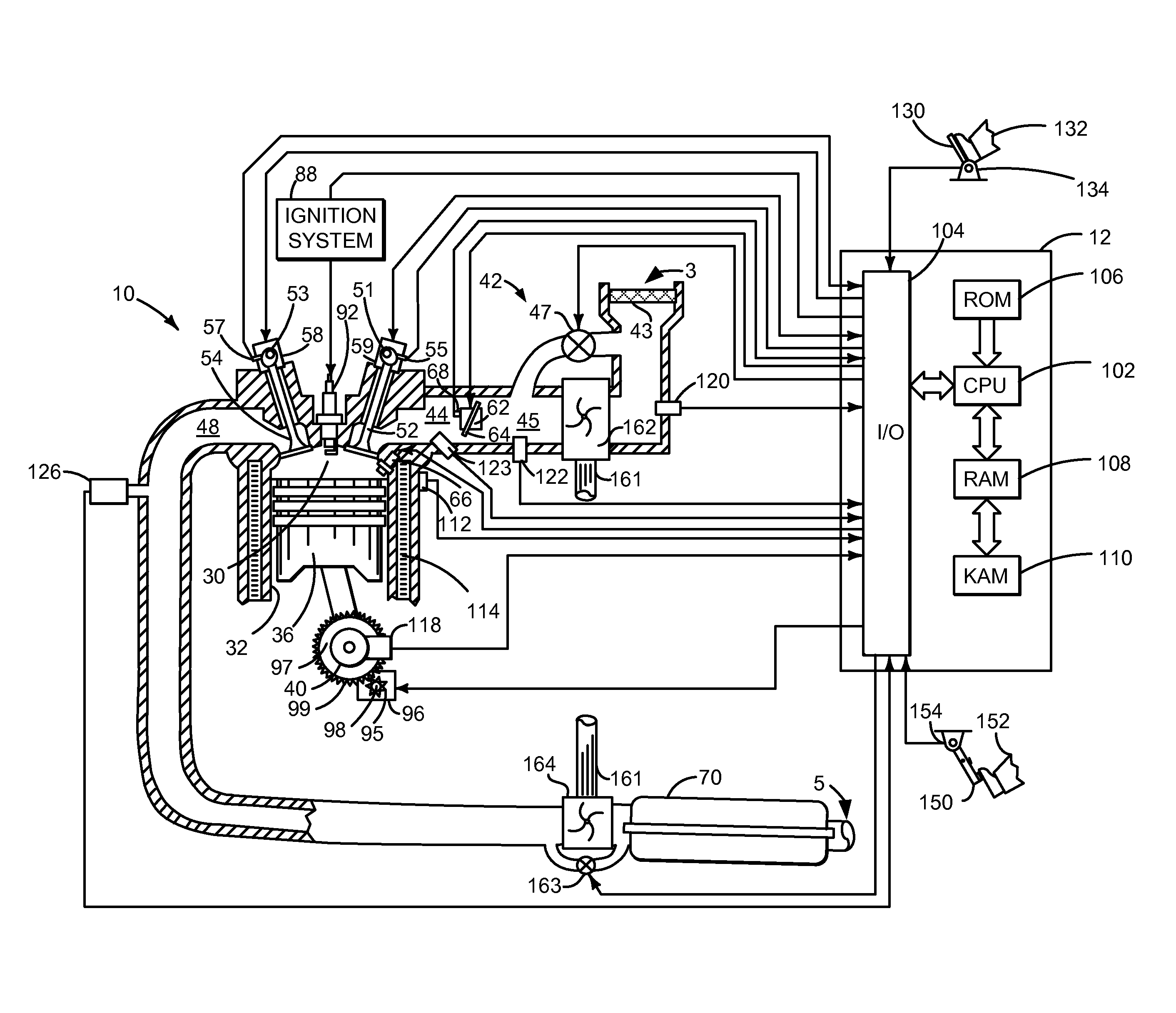
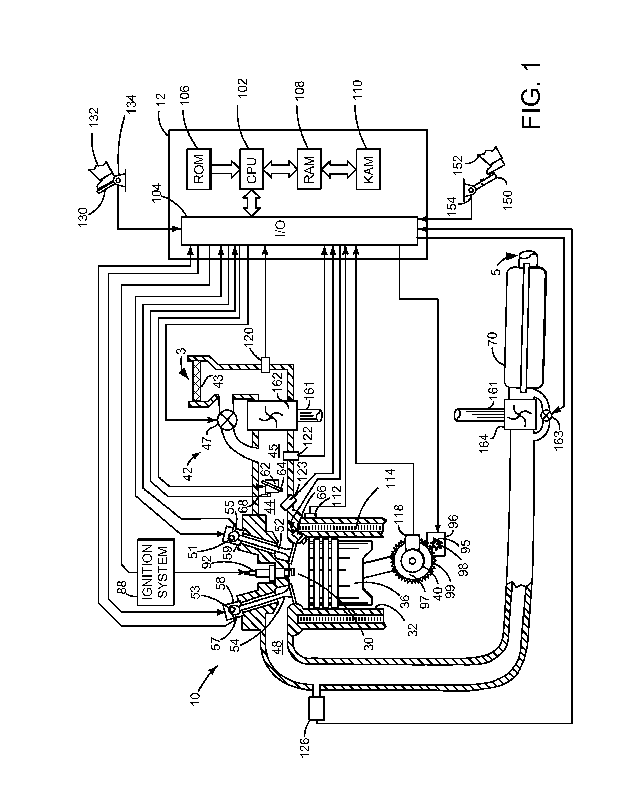
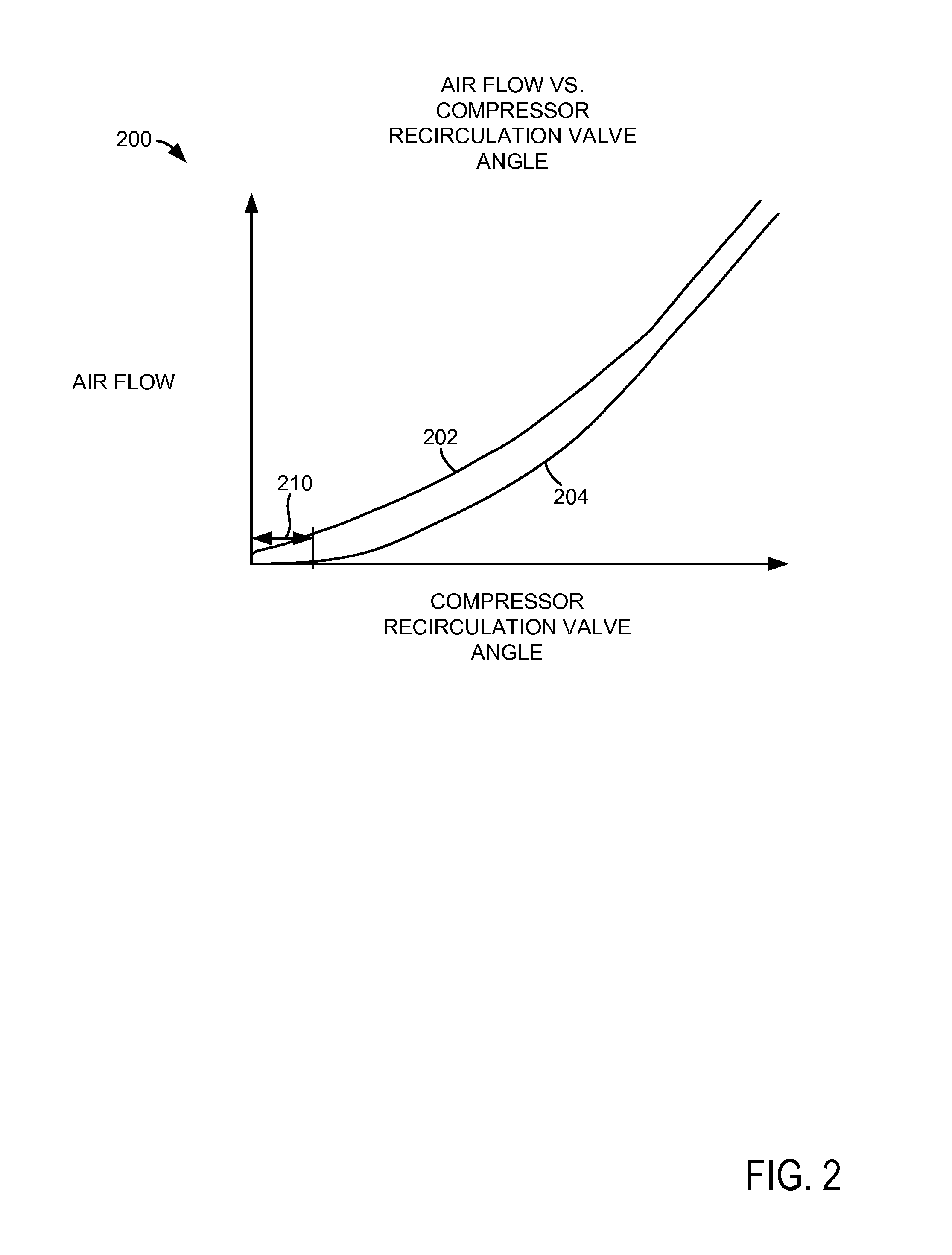
[0013]The present description is related to operating an engine with a compressor recirculation valve. The compressor recirculation valve may be incorporated into an engine as is shown in FIG. 1. The compressor recirculation valve may exhibit flow characteristics similar to those shown in FIG. 2. The engine may be part of a system that includes a controller with instructions for the method of FIG. 3. The system of FIG. 1 and the method of FIG. 3 may operate to provide the sequence of FIG. 4.

[0014]Referring to FIG. 1, internal combustion engine 10, comprising a plurality of cylinders, one cylinder of which is shown in FIG. 1, is controlled by electronic engine controller 12. Engine 10 includes combustion chamber 30 and cylinder walls 32 with piston 36 positioned therein and connected to crankshaft 40. Flywheel 97 and ring gear 99 are coupled to crankshaft 40. Starter 96 (e.g., low voltage (operated with less than 30 volts) electric machine) includes pinion shaft 98 and pinion gear 95...


PUM


Abstract

Systems and methods for compensating for deposits that may accumulate within a compressor recirculation valve positioned in parallel with a turbocharger compressor are presented. The systems and methods adjust actuators to maintain engine operation such that it may be more difficult for a driver to become aware that a compressor recirculation valve diagnostic is being executed.

Description

FIELD[0001]The present description relates to methods and a system for compensating sludge that may accumulate within a compressor recirculation valve. The methods and systems may be particularly useful in engines having turbochargers or superchargers.BACKGROUND AND SUMMARY[0002]A supercharged or turbocharged engine includes a compressor for increasing an amount of air flowing through the engine. The engine's output power may increase when the amount of air flowing through the engine is increased. In particular, the engine's fuel flow amount may be proportionately increased with the engine's air flow amount to increase engine power. The turbocharger's compressor increases air pressure in the engine's intake system so that air flow through the engine may be increased. However, if driver demand torque decreases, it may not be desirable to operate the engine with a higher pressure in the engine intake system because the higher air pressure may make it more difficult to control engine a...

Claims


Application Information

Patent Timeline
Patent Type & Authority Applications(United States)
IPC IPC(8): F02B37/18F02D41/00
CPCF02B37/186F02D2041/001F02D41/0007F02B37/16F02D41/22F02D41/18Y02T10/12
Inventor BANKER, ADAM NATHANOSSAREH, HAMID-REZAXIAO, BAITAO
Owner FORD GLOBAL TECH LLC
Why Eureka
Try Eureka