Turbine engine control system

Inactive Publication Date: 2016-06-16
SIEMENS AG
View PDF15 Cites 2 Cited by
  • Summary
  • Abstract
  • Description
  • Claims
  • Application Information

AI Technical Summary

Benefits of technology

[0005]It is an objective of the present invention to reduce or eliminate carbon deposits in the combustion system. It is another object of the present invention to reduce or eliminate the requirement to strip, clean and overhaul burners and other combustion system components, particularly, after only a short period of liquid fuel operatio

Problems solved by technology

However, at these relatively low loads the burner geometry is not optimised and along with relatively low fuel pressures poor atomisation of the liquid spray occurs in the combustor unit.
Poor atomisation of the liquid results in unburned fuel which can be deposited on components in the combustion unit.
In particular, these carbon deposits can build up on burner compo

Method used


Image

  • Turbine engine control system
  • Turbine engine control system
  • Turbine engine control system

Examples


Example

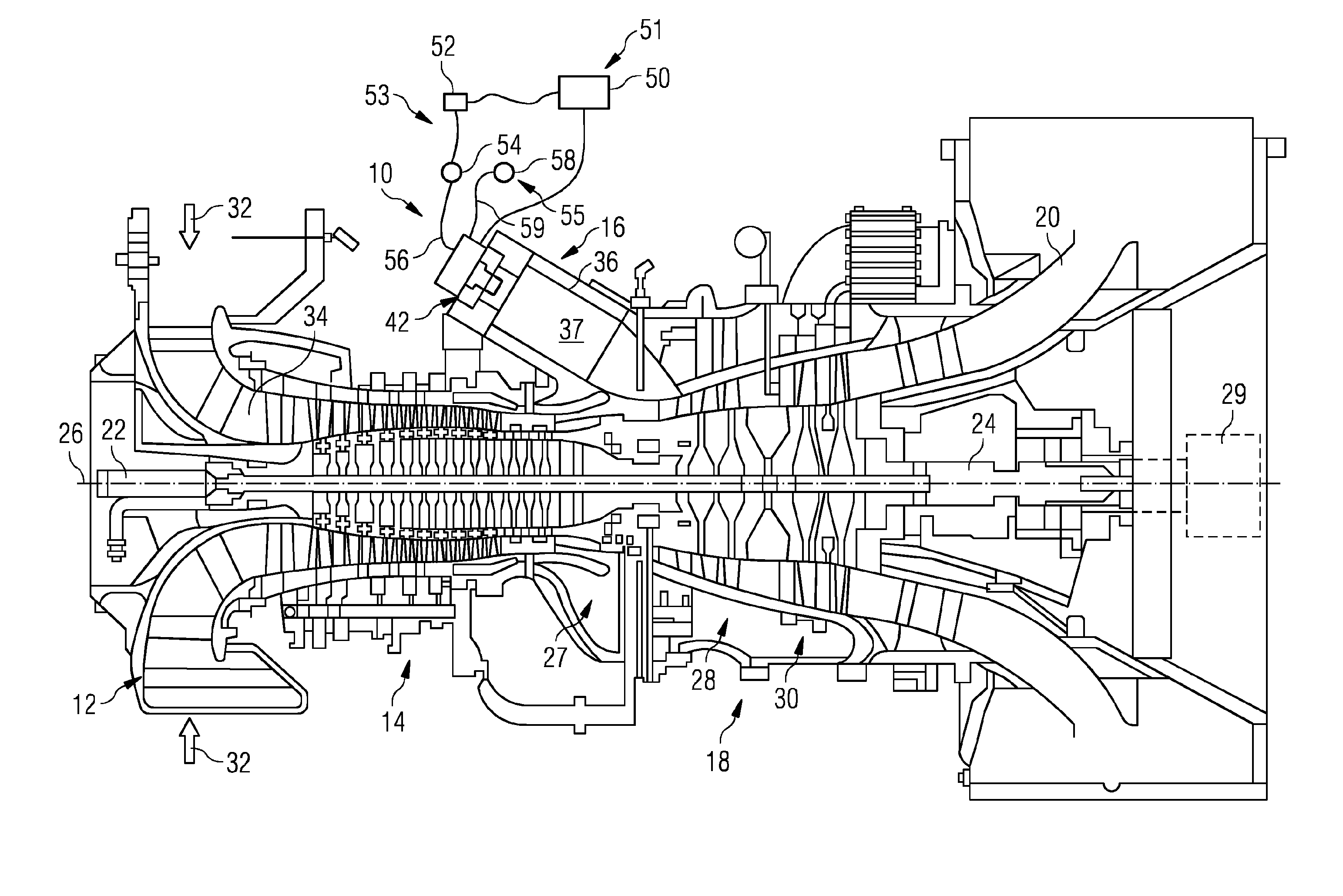
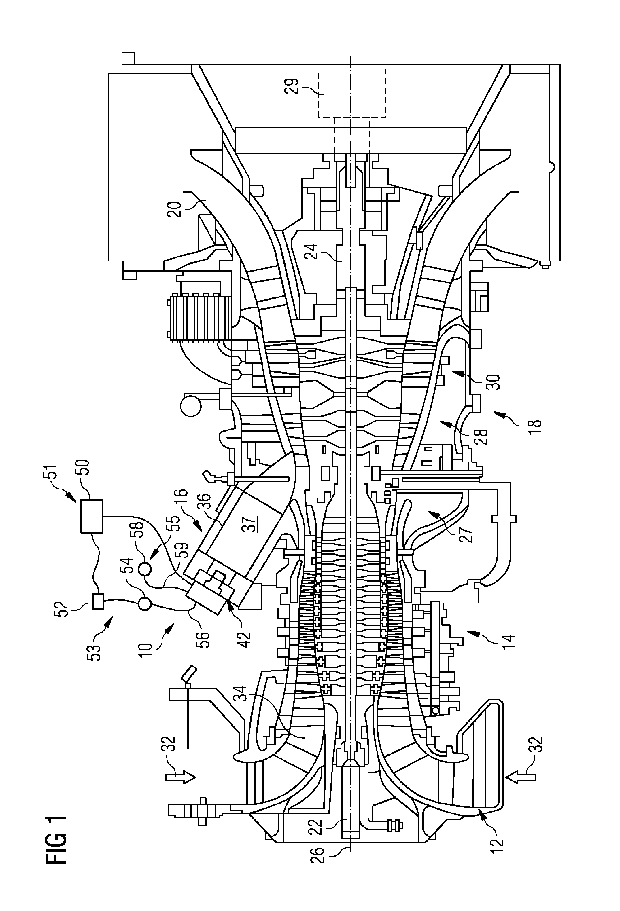
[0030]FIG. 1 is a schematic illustration of a general arrangement of a turbine engine 10 having an inlet 12, a compressor 14, a combustor system 16, a turbine system 18, an exhaust duct 20 and a twin-shaft arrangement 22, 24. The turbine engine 10 is generally arranged about an axis 26 which for rotating components is their rotational axis. The arrangements 22, 24 may have the same or opposite directions of rotation. The combustion system 16 comprises an annular array of combustor units 36, only one of which is shown. In one example, there are six combustor units evenly spaced about the engine. The turbine system 18 includes a high-pressure turbine 28 drivingly connected to the compressor 14 by a first shaft 22 of the twin-shaft arrangement. The turbine system 18 also includes a low-pressure turbine 30 drivingly connected to a load 29 via a second shaft 24 of the twin-shaft arrangement.

[0031]The terms radial, circumferential and axial are with respect to the axis 26. The terms upstr...


PUM


Abstract

A method of operating a turbine engine, the turbine engine having an inlet, a shaft, a turbine, a control system, a fuel system and a modular liquid fuel burner system having at least two interchangeable liquid burners and a liquid-fuel manifold. The control system controls a fuel supply via the liquid-fuel manifold to the burners dependent on demanded output power. The at least two interchangeable liquid fuel burners have different operating power output ranges and having at least a high power output liquid fuel burner and a low power output liquid fuel burner. The method of operating the turbine engine includes the steps of controlling a liquid fuel supply to the high power output burner for a high power output having a turbine entry temperature limit and controlling a liquid fuel supply to the low power output burner for a low power output having a liquid fuel manifold pressure limit.

Description

CROSS REFERENCE TO RELATED APPLICATIONS[0001]This application is the US National Stage of International Application No. PCT / EP2014 / 063670 filed Jun. 27, 2014, and claims the benefit thereof. The International Application claims the benefit of Great Britain Application No. GB 1312974.7 filed Jul. 19, 2013. All of the applications are incorporated by reference herein in their entirety.FIELD OF INVENTION[0002]The present invention relates to a turbine engine control system for controlling the power output dependent on fuel pressure and ambient temperature for any given capacity of a liquid fuel burner.BACKGROUND OF INVENTION[0003]Dual-fuel industrial gas turbine engines are capable of operating their burner systems with liquid or gas fuels. Some conventional turbine engines operate on liquid fuel for short periods during commissioning and can also be expected to run at low power when an associated gas plant is not operational, for example down for maintenance. This tends to be for a pe...

Claims


Application Information

Patent Timeline
IPC IPC(8): F02C7/264F02C7/22
CPCF02C7/222F02C7/264F02C7/228F02C9/28F02C9/48
Inventor DOLMANSLEY, TIMOTHYHEADLAND, PAULSKIPPER, DORIANSMITH, MICHAEL
Owner SIEMENS AG
Why Eureka
Try Eureka