Radar detection of endo-clutter high-value targets using tracker feedback

a tracker feedback and target technology, applied in the field of target detection, can solve the problems of low snr value, smearing and displacement of the target's energy signal, and trade-offs of mti-mode radars

Active Publication Date: 2016-06-16
BAE SYST INFORMATION & ELECTRONICS SYST INTERGRATION INC
View PDF0 Cites 28 Cited by
  • Summary
  • Abstract
  • Description
  • Claims
  • Application Information

AI Technical Summary

Benefits of technology

[0009]An embodiment provides a system for radar detection of endo-clutter targets using tracker feedback, comprising selecting an endo-clutter target to be tracked; tracking the endo-clutter target using a synthetic aperture radar (SAR) having a plurality of antenna channels; for each of a plurality of coherent processing intervals (CPIs) employing polar-format SAR pre-processing in a processor of a radar receiver device of motion-compensated phase history data for each antenna channel; determining a location of a processed SAR image chip by converting track location and velocity into SAR image coordinates, wherein a size of the chip is proportional to a tracker error ellipse; compensating for defocusing due to target motion using an efficient one-dimensional moving reference processing (MRP) search over a single target defocus parameter expressed as a known function of the endo-clutter target and platform location, velocity, and acceleration; and performing space-time adaptive processing (STAP) on the SAR image chip using adaptive spatial antenna and temporal MRP degrees of freedom. In embodiments performing space-time excision and calculation of a likelihood metric to select a single detection to be used to update the tracker; and performing a polar formatting procedure to define a mapping from wavelength and slow-time to k-space. In other emb

Problems solved by technology

However MTI-mode radars suffer from tradeoffs between the small integration time (that leads to low SNR values and coarse resolutions) as compared to the number of regions that can be observed.
Furthermore, MTI systems can only detect velocities in a single direction, which allow for evasive maneuvers to avoid detection.
SAR was designed to image stationary scenes, consequently, moving targets cause phase errors in the reconstruction of a SAR image that lead to smearing and displacement of a target's energy signal.
Previous attempts to use SAR for moving target detection involved approache

Method used


Image

  • Radar detection of endo-clutter high-value targets using tracker feedback
  • Radar detection of endo-clutter high-value targets using tracker feedback
  • Radar detection of endo-clutter high-value targets using tracker feedback

Examples


Embodiment Construction

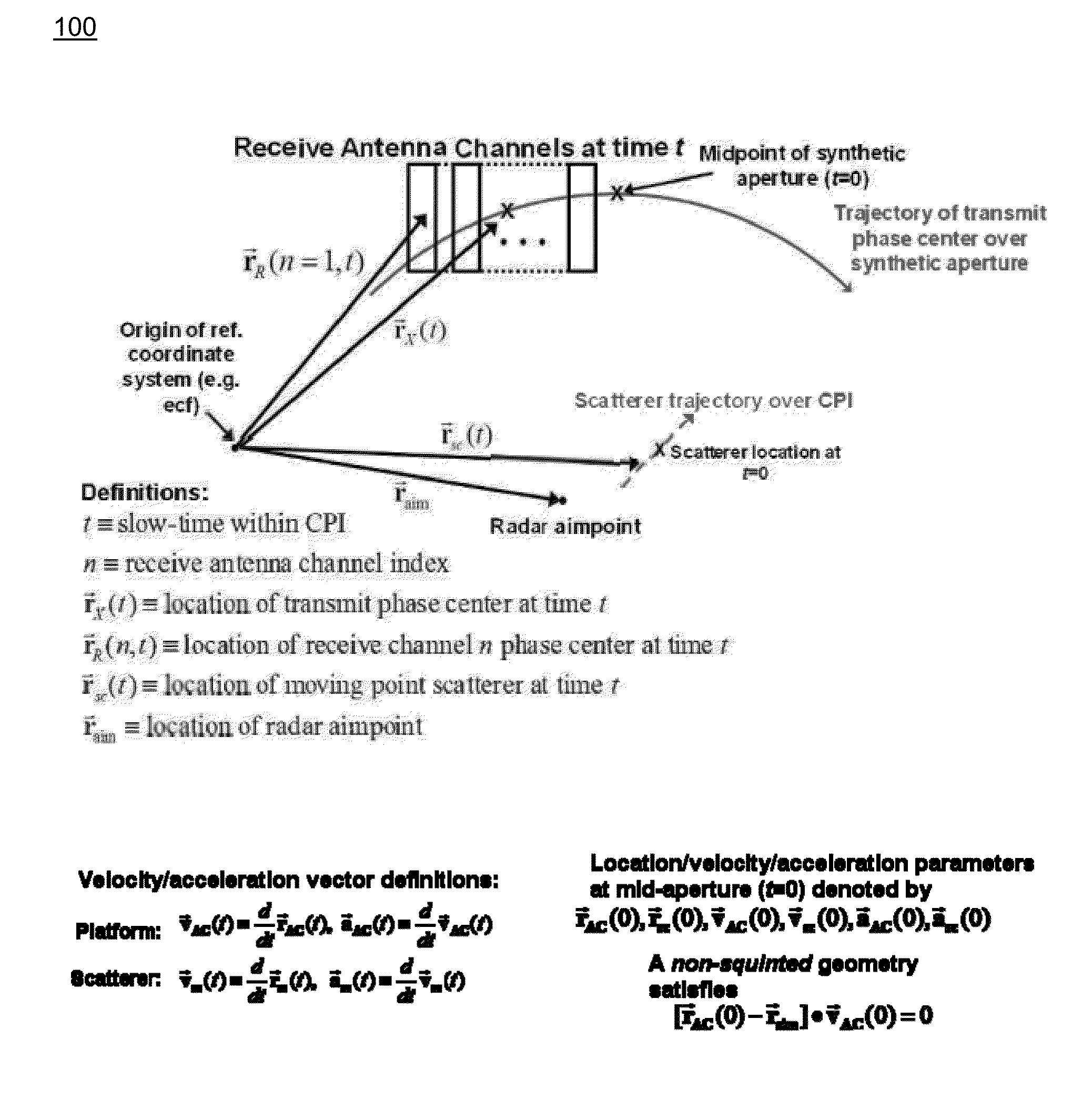
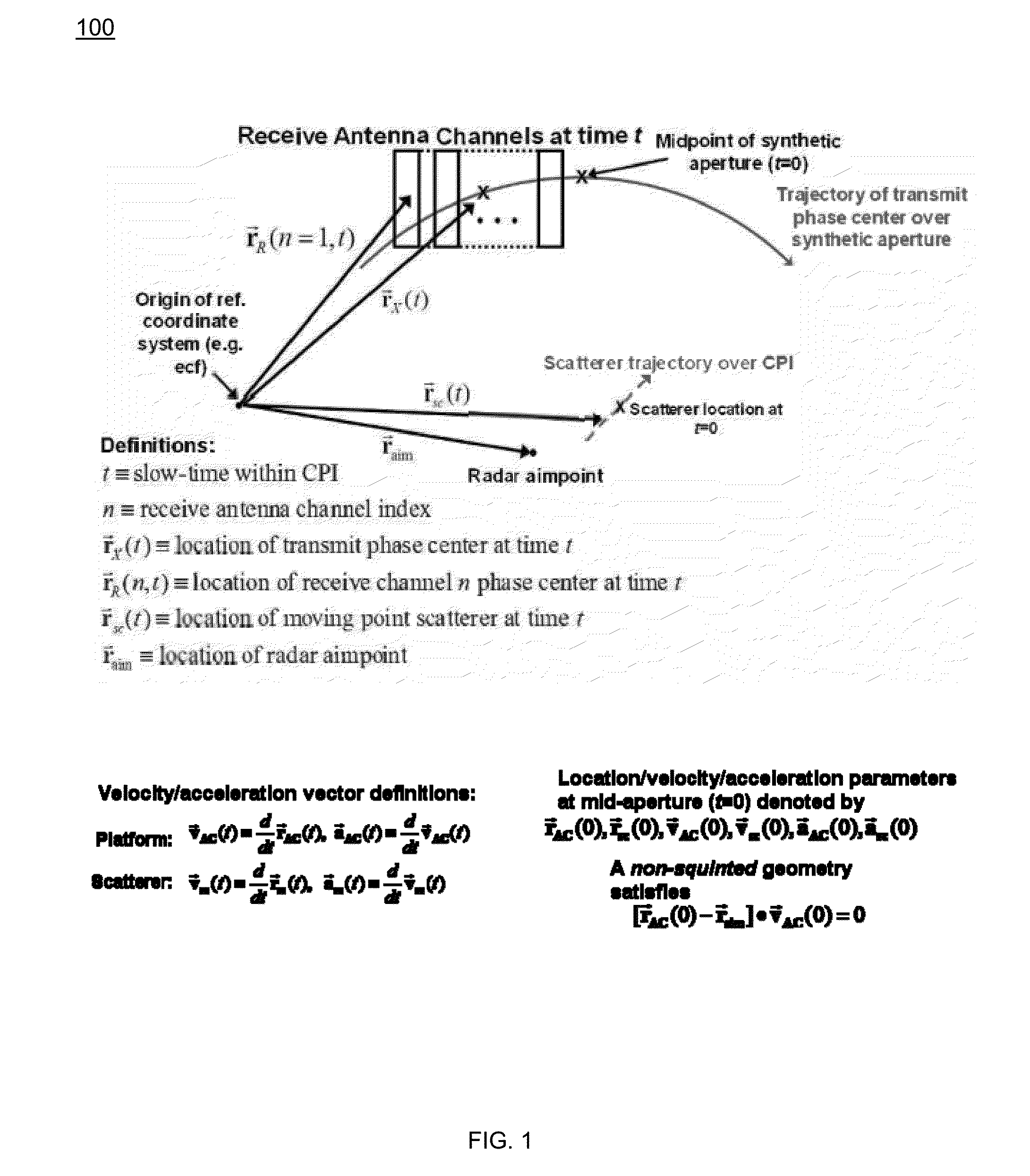
[0037]The present invention is an “in-the-loop” method for detecting, geolocating, and tracking in main-beam clutter (i.e. endo-clutter, not noise-only exo-clutter) targets in multi-channel Synthetic Aperture Radar (SAR) data. The approach employs tracker feedback in the detection processing in order to maximize tracking performance on a single target, which is assumed to be identified at some initial time. To compensate for platform-induced range and Doppler dispersion, embodiments employ SAR pre-processing of motion-compensated phase history data for each antenna channel. The location of the processed SAR image chip on each coherent processing interval (CPI) is determined by converting track location and velocity into SAR image coordinates. The size of the small extracted sub-image (chip) is a function of the tracker error ellipse, allowing for smaller image chips when the target motion state is known accurately. Embodiments compensate for defocusing due to target motion using an ...


PUM


Abstract

A radar signal target detection and display system employs feedback to produce improved detection and tracking. Portions of the radar images for each antenna channel to search for the target of interest are defined using the track state to define the center of the search region and using the track covariance matrix to define the size of the region. Moving reference processing (MRP) is performed. MRP employs a search centered on the motion state derived from the detection sent to the tracker on the previous coherent processing interval (CPI). Space-time adaptive processing (STAP) is employed on each CPI using a unique set of adaptive degrees of freedom (DOFs) derived from pre-MRP and post-MRP complex radar image amplitudes for each antenna channel.

Description

RELATED APPLICATIONS[0001]This application claims the benefit of U.S. Provisional Application No. 62 / 022,437 filed Jul. 9, 2014. This application is herein incorporated by reference in its entirety for all purposes.STATEMENT OF GOVERNMENT INTEREST[0002]This invention was made with United States Government support under Contract No. FA8650-07-D-1227 / 0001 awarded by the U.S. Army. The United States Government has certain rights in this invention.FIELD OF THE INVENTION[0003]The invention relates to radar detection of targets, and more particularly, to high-value target tracking using multi-channel radar. Still more particularly, the invention relates to the tracking of highly maneuverable, low Radar Cross Section (RCS) targets such as civilian vehicles and dismounts, even in the presence of bright, heterogeneous clutter such as in a semi-urban environment in high traffic scenarios.BACKGROUND OF THE INVENTION[0004]Current radar systems are able to operate in several distinct modes, depe...

Claims


Application Information

Patent Timeline
IPC IPC(8): G01S13/90
CPCG01S13/9029G01S13/5242
Inventor OWIRKA, GREGORY J.PAGE, DOUGLAS A.KRAGH, THOMAS J.NICHOLS, HOWARD E.
Owner BAE SYST INFORMATION & ELECTRONICS SYST INTERGRATION INC
Why Eureka
Try Eureka