Vibrating device and electronic device using same

a technology which is applied in the field of vibrating device and electronic device using same, can solve the problem of not enough sound volume required by a speaker, and achieve the effect of improving installationability and slimness, and not increasing the thickness of the vibrating devi

Active Publication Date: 2016-06-16
TAIYO YUDEN KK
View PDF2 Cites 20 Cited by
  • Summary
  • Abstract
  • Description
  • Claims
  • Application Information

AI Technical Summary

Benefits of technology

[0010]According to the present invention, there are a first transparent plate, a second transparent plate placed on one side of the first transparent plate and having a storage part formed in the thickness direction on the side joined to the first transparent plate, and a piezoelectric vibrating element placed in the storage part of the second transparent plate and joined to the first transparent plate, where the modulus of elasticity of the second transparent plate is lower than the modulus of elasticity of the first transparent plate. This allows enough vibration needed for the haptic function to be transmitted even when the force or displacement is small, and also provides a vibrating device having a speaker (receiver) function for generating audible sound. In addition, a haptic function and speaker function can be added without increasing the thickness of the vibrating device, which results in improved installability and slimness.

Problems solved by technology

In other words, it presents a problem of not outputting enough sound volume required by a speaker.

Method used


Image

  • Vibrating device and electronic device using same
  • Vibrating device and electronic device using same
  • Vibrating device and electronic device using same

Examples


example 1

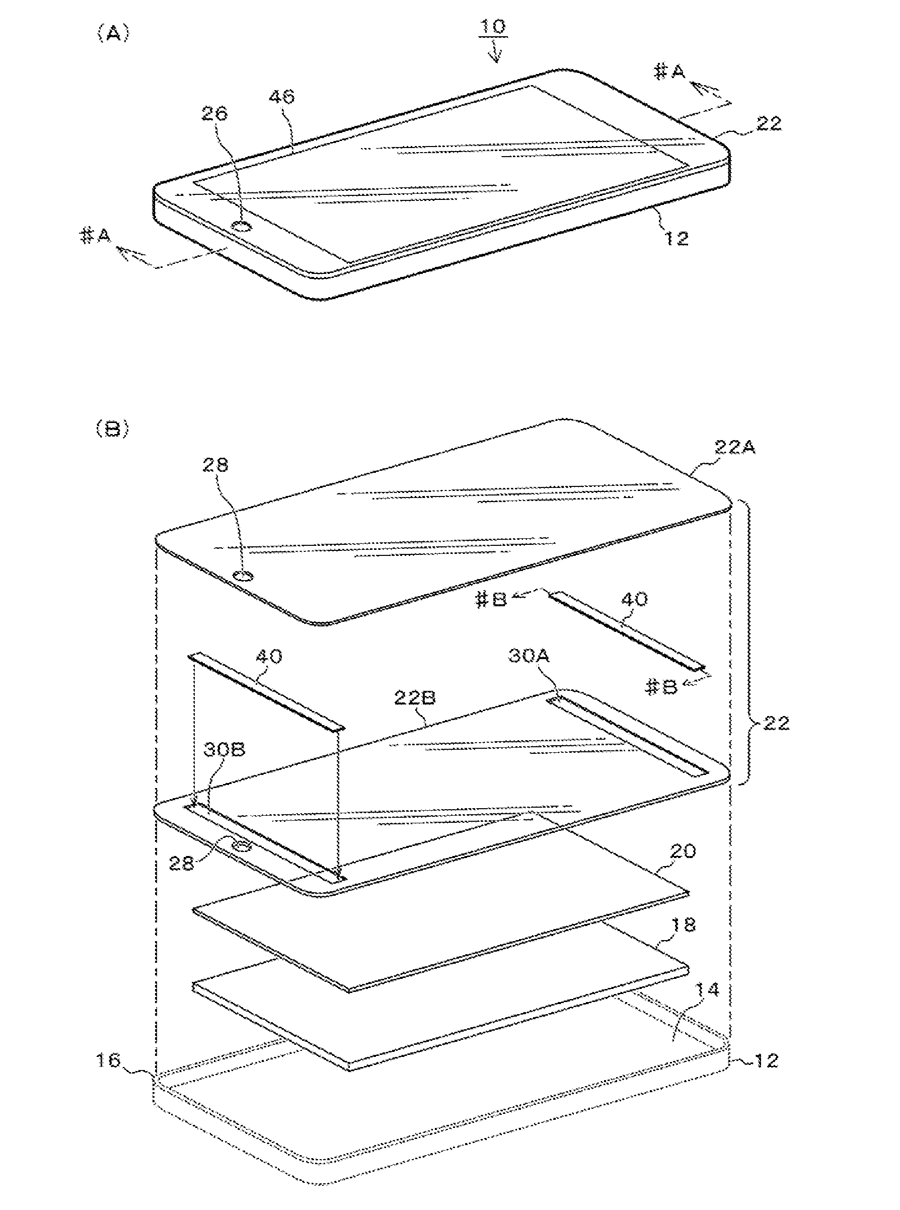
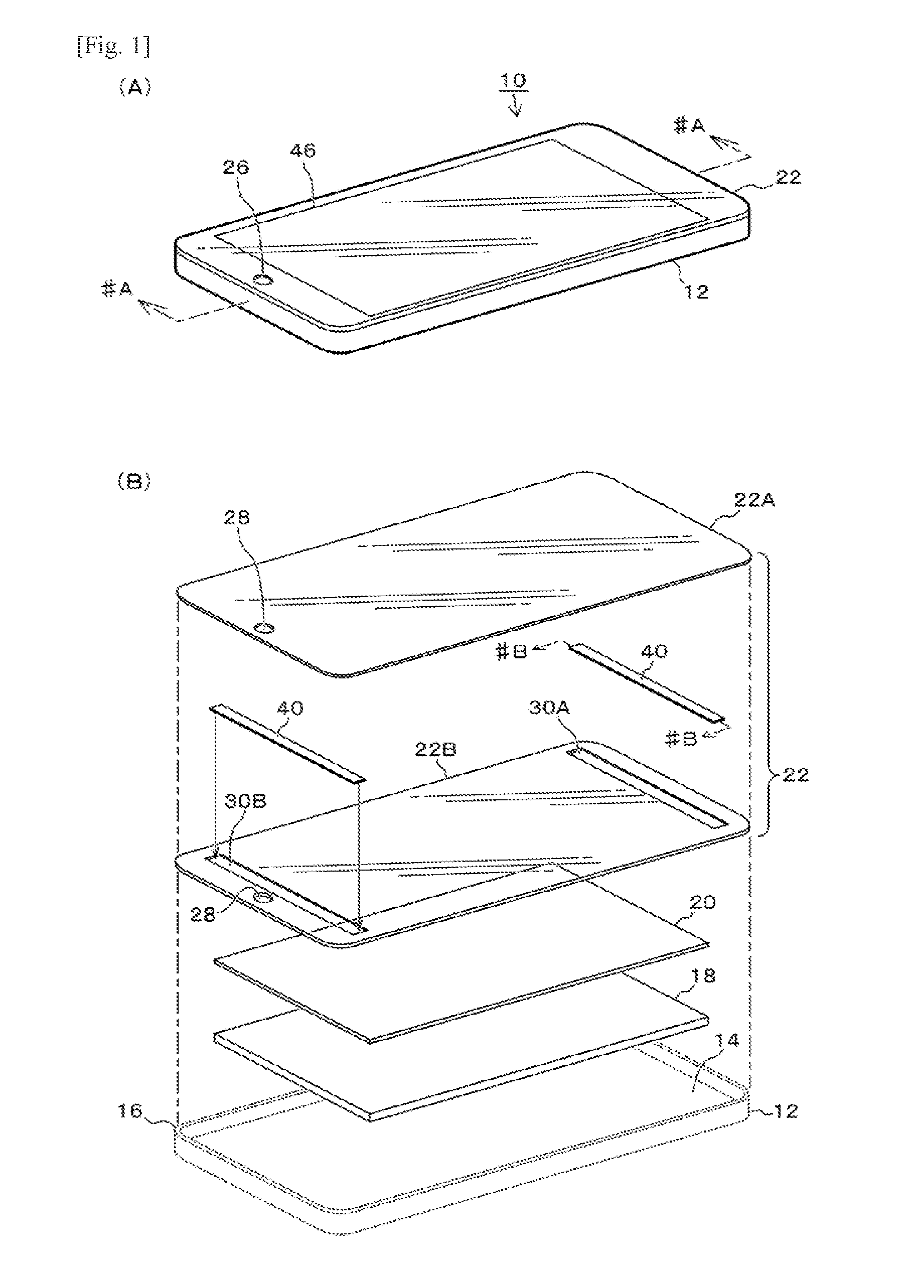
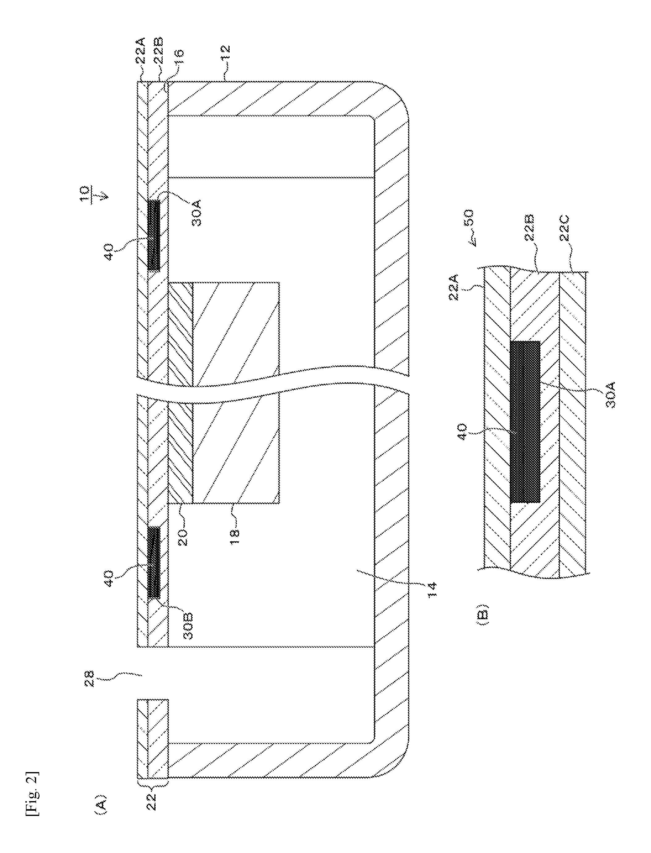
[0017]First, Example 1 of the present invention is explained by referring to FIG. 1 to FIG. 4. The present invention relates to an art of installing a haptic function that allows for perception of inputs through tactile sensations, and a panel speaker function, to electronic devices having a display device and a touch panel function accompanying the display device, such as mobile phones and smartphones as well as car navigation systems and game consoles. In this example, a smartphone is explained as an example of the aforementioned electronic devices. FIG. 1 provides drawings showing the smartphone in this example, where (A) is an overall perspective view of the exterior and (B) is an exploded perspective view of the panel display part. FIG. 2 (A) is a section view of the part where the piezoelectric vibrating element is installed, cut along line #A-#A of FIG. 1 (A) above and viewed from the direction of the arrows, while FIG. 2 (B) is a section view of the protective panel in an ex...


PUM


Abstract

In an embodiment, a surface of a smartphone 10 is covered with a transparent protective panel 22 supported by rims 16 of a housing 12, and a display device 18 and touch panel 20 are placed in a storage part 14 of the housing 12. The protective panel 22 is constituted by joining a glass plate 22A and resin plate 22B together, and concave parts 30A, 30B are provided on the joining surface side of the resin plate 22B, with piezoelectric vibrating elements 40 placed therein and joined to the glass plate 22A, wherein vibration is transmitted to the surface of the protective panel 22 as surface acoustic waves, demonstrating a haptic function, and also, audible vibration is generated because the modulus of elasticity of the resin plate 22B is lower than that of the glass plate 22A, achieving an operation as a speaker (or receiver).

Description

TECHNICAL FIELD[0001]The present invention relates to a vibrating device with a force feedback function (or haptic function) based on a piezoelectric vibrating element, as well as an electronic device using such vibrating device, and more specifically to improving the property of sound generation from a vibrating surface.BACKGROUND ART[0002]In the field of mobile devices such as smartphones and tablet PCs, the market is starting to see products with a haptic function to create tactile sensations that can be felt by the fingertips. Many of these products comprise a piezoelectric element attached to glass or other material, and are at the current moment still unable to produce enough vibratory displacement with hard glass, etc. In addition, there is a problem that having to attach an element to the back of cover glass limits the installability of the element in the thickness direction.[0003]For example, Patent Literature 1 below describes a structure comprising piezoelectric elements ...

Claims


Application Information

Patent Timeline
Patent Type & Authority Applications(United States)
IPC IPC(8): G06F3/041G06F3/16G06F3/01
CPCG06F3/0412G06F3/16G06F3/016G06F3/041H04M1/02H04M1/0266H04M19/047B06B1/0603B06B1/0611H04R17/00H04R2499/11Y02D30/70G06F2203/04103G06F3/01
Inventor WATANABE, YOSHIYUKIISHII, SHIGEO
Owner TAIYO YUDEN KK
Why Eureka
Try Eureka