Device for the additive manufacture of a component

a technology for components and devices, applied in the direction of additive manufacturing processes, manufacturing tools, instruments, etc., can solve the problems of inferior component quality and undefined adjustment of focus positions, and achieve the effect of high precision, precise determination of focus areas, and rapid and simple determination of focus areas

Inactive Publication Date: 2016-06-23
MTU AERO ENGINES GMBH
View PDF5 Cites 51 Cited by
  • Summary
  • Abstract
  • Description
  • Claims
  • Application Information

AI Technical Summary

Benefits of technology

[0015]In an advantageous embodiment of the invention, it is provided that the power of the high-energy beam is adjusted when the cross-sectional geometry is determined, in such a way that the powder layer is not melted and / or sintered at the measurement point. It is reliably assured in this way that the determination of the focus area takes place without intervention in the actual manufacturing process and without damage to already produced component layers.
[0016]In another advantageous embodiment of the invention, it is provided that the focus area of the high-energy beam is determined on the basis of the cross-sectional geometry of the high-energy beam in at least three non-collinear measurement points. This represents a particularly rapid and simple possibility for determining the focus area. In the simplest case of a focus plane, three measurement points are sufficient in order to be able to correctly define the focus plane. In the case of geometrically more complex focus areas, four or more measurement points may be necessary for a clear determination. Preferably, the at least three measurement points are selected in such a way that they are disposed spaced apart from one another as far as possible, since a particularly precise determination of the focus area is assured in this way.
[0017]In another advantageous embodiment of the invention, it is provided that the construction platform is moved relative to the radiation source in order to determine a minimum cross-sectional geometry of the high-energy beam. Although the determination of the focus position at a measurement point can also be carried out basically by a comparison between the determined cross-sectional geometry and a pre-defined cross-sectional geometry, the determination of the optimal focus position by moving the construction platform offers the particular advantage that the minimum cross-sectional geometry is determined directly on the respective component or powder bed, so that individually occurring thermal or mechanical deviations can be better taken into consideration. When the construction platform is moved, the resulting cross-sectional geometry of the high-energy beam is determined. When the minimum cross-sectional geometry is reached, the high-energy beam will be in focus at this measurement point. The measurement point determined in such a way can then be drawn on for further determining the focus area.
[0018]Additional advantages result by moving the construction platform for determining the minimum cross-sectional geometry continuously, and / or at least by the Rayleigh length of the high-energy beam, and / or by at least 20 mm, and / or stepwise by a pre-specified step, in particular by 10% of the Rayleigh length of the high-energy beam. In this way, it is assured that this involves the minimum cross-sectional geometry of the high-energy beam around a global minimum.
[0019]In another advantageous embodiment of the invention, it is provided that at least the examination of whether a deviation is present between the construction surface area and the focus area of the high-energy beam is carried out continuously, and / or at pre-determined time intervals, and / or after each component layer that is produced, and / or prior to a pre-defined component layer, and / or as a function of a heating of the device. In this way, the method according to the invention can be conducted as needed and can be optimally adapted to the respective construction job, whereby, in addition to a high precision and high component quality, minimum time delays are also assured by the examination, and the correction of the alignment of focus area and construction surface area to one another, which may be necessary, is also assured.

Problems solved by technology

It has been observed, however, that such devices are subject to a drift that is presumably thermally or mechanically caused, and this drift can lead to an undefined maladjustment of the focus position during the manufacturing process.
This maladjustment of the focus position leads to an imprecise exposure profile and thus to disruptions in the process as well as material defects, from which results an inferior component quality.

Method used


Image

  • Device for the additive manufacture of a component
  • Device for the additive manufacture of a component
  • Device for the additive manufacture of a component

Examples


Embodiment Construction

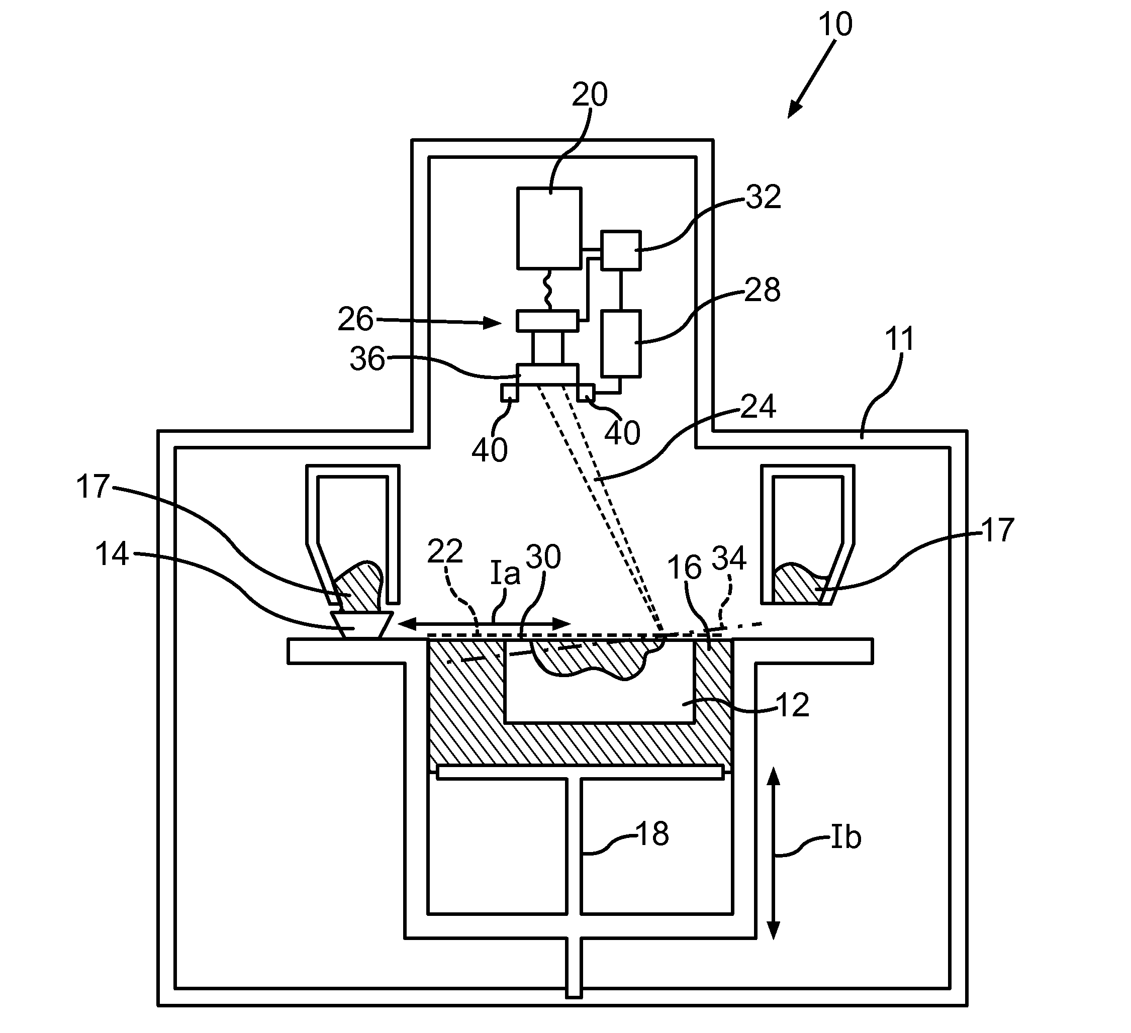
[0025]FIG. 1 shows a schematic sectional view of an exemplary embodiment of a device 10 according to the invention for the additive manufacture or repair of a component 12, which is designed presently as a rotating blade of a turbine of an aircraft engine. The device 10 comprises a process chamber 11, in which a coating device 14 that can be moved according to double arrow Ia for producing a powder layer 16 from a component material 17 is disposed on a construction platform 18. In its turn, the construction platform 18 can be moved according to double arrow Ib, and in addition, can be optionally designed as rotatable and / or pivotable. In equipping the device 10, the construction platform 18 can be aligned with the coating device 14 by rotation about the x- and y-axes, so that a uniform application of the powder layer 16 over the construction platform 18 can be assured. This may be necessary, since the upper side and the underside of the construction platform 18 are often not exactly...


PUM

PropertyMeasurementUnit
Rayleigh lengthaaaaaaaaaa
wavelengthaaaaaaaaaa
Rayleigh lengthaaaaaaaaaa

Abstract

The invention relates to a device (10) for the additive manufacture of a component (12), comprising at least one coating device (14) for producing a powder layer (16) on a construction platform (18); at least one radiation source (20), in particular a laser, for producing a high-energy beam (24), by means of which the powder layer (16) in a construction surface area (22) can be melted and/or sintered locally to form a component layer (30); at least one deflection device (26), by means of which the high-energy beam (24) can be deflected onto different regions of the powder layer (16) and can be focused on the construction surface area (22); at least one measurement system (28), by means of which a cross-sectional geometry of the high-energy beam (24) on the powder layer (16) and/or the component layer (30) can be determined; and at least one equilibration device (32).

Description

BACKGROUND OF THE INVENTION[0001]The invention relates to a device for the additive manufacture of a component as well as a method for operating such a device.[0002]Devices for the additive manufacture of components, such as laser-beam melting systems, for example, operate with a focused high-energy beam or laser beam that melts and / or sinters powder-form initial material that has been introduced as a layer onto a construction platform, to form a solid layer of a component. In this case, the correct and uniform focusing of the high-energy beam over the entire construction platform is of great importance. The cross-sectional geometry of the high-energy beam and thus its local energy density that are part of the core values of the additive manufacturing method are influenced by the focus. It is known from GB 2490143 A to arrange a beam splitter in the beam path of the high-energy beam, in order to determine the cross-sectional geometry of the high-energy beam. The cross-sectional geom...

Claims


Application Information

Patent Timeline
Patent Type & Authority Applications(United States)
IPC IPC(8): B22F7/02
CPCB33Y30/00B22F7/02B23K26/032G02B7/287G02B7/36B23K26/342B23K26/042B33Y10/00B23K26/046B23K26/0738B23K26/083B23K26/127B23K26/082B29C64/393B29C64/153Y02P10/25B22F10/38B22F10/31B22F10/28B22F10/36B22F12/49B22F12/46B22F12/44B22F12/37B22F12/90
Inventor LADEWIG, ALEXANDERSCHLOTHAUER, STEFFENLIEBL, CHRISTIANSCHLICK, GEORGFISSER, MAXIMILIAN
Owner MTU AERO ENGINES GMBH
Why Eureka
Try Eureka