Eureka AIR delivers breakthrough ideas for toughest innovation challenges, trusted by R&D personnel around the world.

Position controller of feed axis in machine tool

Active Publication Date: 2016-06-23
OKUMA CORP
View PDF5 Cites 6 Cited by
  • Summary
  • Abstract
  • Description
  • Claims
  • Application Information

AI Technical Summary

Benefits of technology

The invention allows for the correction of tool edge runouts without needing an external device or prior measurement. This helps to prevent tool chipping and can be done at a lower cost.

Problems solved by technology

The heights of the attached cutting edges are not uniform in this tool since a surface to which the cutting edge of the tool is attached varies and machining accuracy is different depending on the cutting edge itself.
Therefore, runout amounts (relative installation errors between respective cutting edges) are generated.
This causes problems that a labor is taken for the work and an external device is required separately from the controller in the machine tool.

Method used


Image

  • Position controller of feed axis in machine tool
  • Position controller of feed axis in machine tool
  • Position controller of feed axis in machine tool

Examples


Embodiment Construction

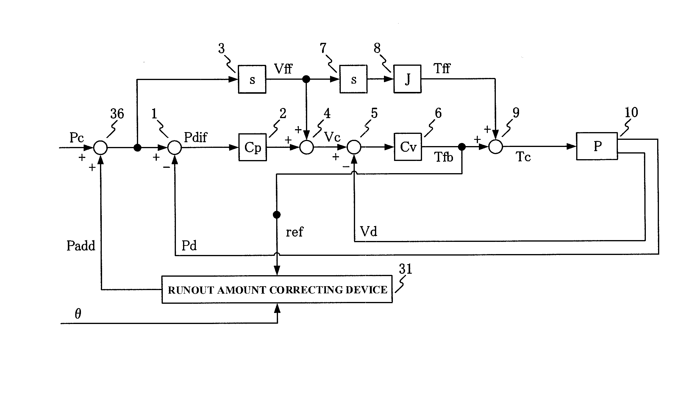
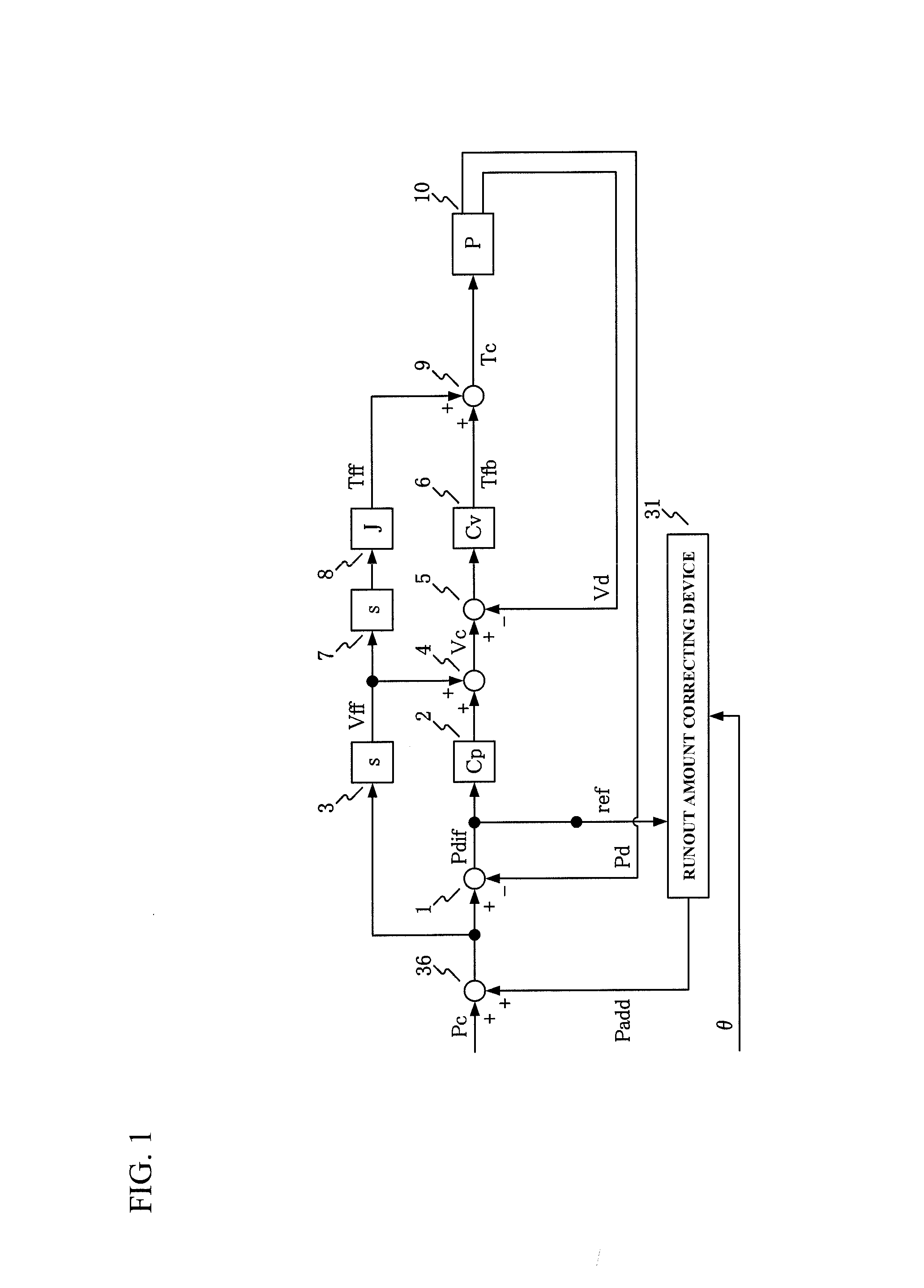
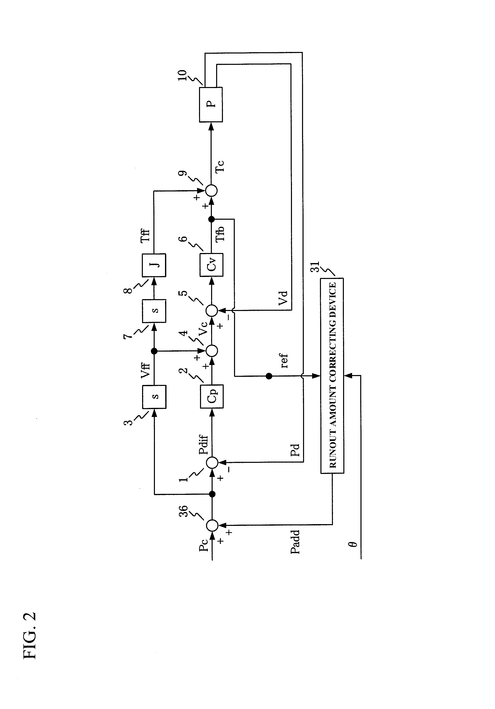
[0025]The following describes embodiments of the present invention with reference to the drawings.

[0026]FIG. 1 to FIG. 3 are block diagrams illustrating position controllers of feed axes for a machine tool of respective Embodiments 1 to 3 of the present invention. Common to the respective embodiments, for example, the following well-known machine tool is considered. The machine tool includes a main spindle head on a front face of a column disposed upright on a bed. The main spindle head has a main spindle to which a tool is attached. The main spindle head is controlled movable in the X-axis direction and the Z-axis direction by an X-axis control unit and a Z-axis-control unit. A table is disposed on the bed so as to be controlled movable in the Y-axis direction by a Y-axis control unit such that a workpiece can be secured on the table. The tool used here includes a plurality of cutting edges circumferentially disposed on a concentric circle at equal intervals.

[0027]In FIG. 1 to FIG....


PUM


Abstract

A position controller includes a position detector, a speed command operator, a first adder, a torque command operator, a second adder, a drive unit, a runout amount correcting device, and a third adder. The runout amount correcting device is configured to employ a value related to deviation between a command value and a detection value in physical quantity of a movable part as a reference signal. The runout amount correcting device is configured to calculate a position correction amount from rotation angle information of the main spindle and the reference signal. The runout amount correcting device is configured to estimate a runout amount of a cutting edge of the tool from the reference signal. The runout amount correcting device is configured to calculate the position correction amount such that influences of the respective cutting edges appearing in the reference signal are leveled.

Description

BACKGROUND[0001]This application claims the benefit of Japanese Patent Application Number 2014-257722 filed on Dec. 19, 2014 and Japanese Patent Application Number 2015-137975 filed on Jul. 9, 2015, the entirety of which is incorporated by reference.TECHNICAL FIELD[0002]The present invention relates to a position controller of a feed axis. The position controller controls the position of the feed axis considering runout amounts of cutting edges of a tool during machining of a machine tool, especially during heavy cutting of a hard-to-cut material, such as a titanium alloy. This restrains a chatter vibration and a chipping of tool.RELATED ART[0003]When a hard-to-cut material is machined by milling, a tool, to which detachable cutting edges called “Throw-away” or “Insert” are attached, is used for reducing machining costs. The heights of the attached cutting edges are not uniform in this tool since a surface to which the cutting edge of the tool is attached varies and machining accura...

Claims


Application Information

Patent Timeline
IPC IPC(8): B23Q15/013G05B19/19B23Q15/12
CPCB23Q15/013G05B2219/37506G05B19/19B23Q15/12B23Q11/04B23Q15/08B23Q17/00B23Q17/12G05B19/404G05B2219/49168Y02P90/02
Inventor MIYAJI, MASASHI
Owner OKUMA CORP
Why Eureka
Eureka Blog
Learn More