System and Method for Assisting in the Manufacture of a Wind Turbine Blade Shell

a technology of wind turbine blades and manufacturing methods, which is applied in the manufacture of final products, machines/engines, butter, etc., can solve the problems of increasing the risk of errors, increasing the use of large moulds, and increasing the complexity of laying out fibre mats and further to obtain proper wetting of fibre materials, so as to reduce the risk of errors occurring, improve the quality of wind turbine blade parts, and reduce the cycle time of various processes

Active Publication Date: 2016-06-23
LM WP PATENT HLDG
View PDF6 Cites 12 Cited by
  • Summary
  • Abstract
  • Description
  • Claims
  • Application Information

AI Technical Summary

Benefits of technology

[0006]Accordingly, there is a need for systems and methods that will improve the quality of the wind turbine blade shell parts (or at least decrease the risk of errors occurring) and that can lower the cycle time of the various processes.

Problems solved by technology

This also means that larger moulds have to be used.
Due to the large size, it has become increasingly complicated to lay out the fibre mats and further to obtain proper wetting of the fibre material.
None the less, many of the different processes are still carried out manually, which increases the risk of errors occurring, such as formation of wrinkles in the fibre material or areas of insufficient wetting of the fibre material, which in turn can be detrimental to the mechanical strength of the composite structure and may necessitate that the manufactured wind turbine blade shell part has to scrapped.

Method used


Image

  • System and Method for Assisting in the Manufacture of a Wind Turbine Blade Shell
  • System and Method for Assisting in the Manufacture of a Wind Turbine Blade Shell
  • System and Method for Assisting in the Manufacture of a Wind Turbine Blade Shell

Examples


Embodiment Construction

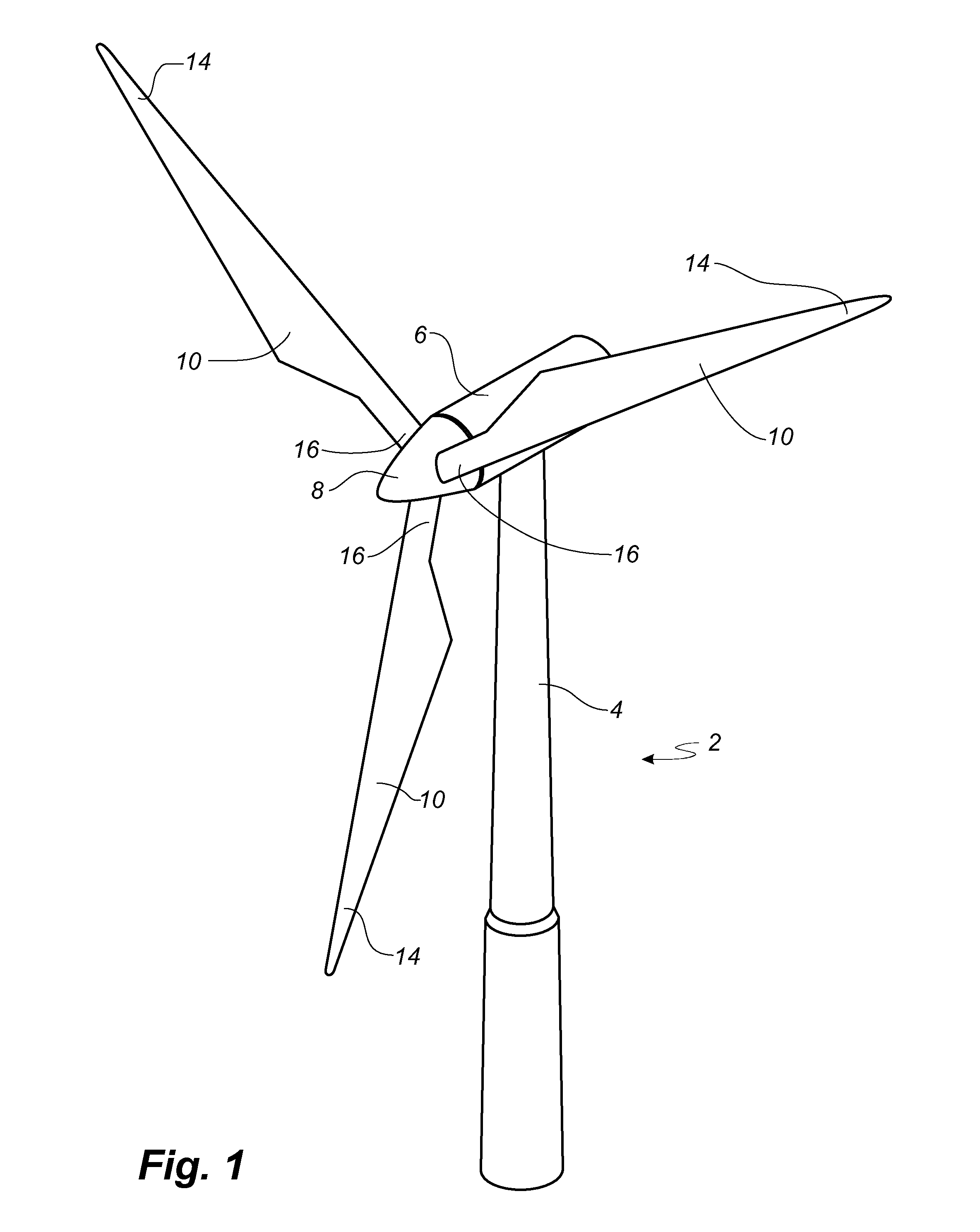
[0096]FIG. 1 illustrates a conventional modern upwind wind turbine 2 according to the so-called “Danish concept” with a tower 4, a nacelle 6 and a rotor with a substantially horizontal rotor shaft. The rotor includes a hub 8 and three blades 10 extending radially from the hub 8, each having a blade root 16 nearest the hub and a blade tip 14 furthest from the hub 8. The rotor has a radius denoted R.

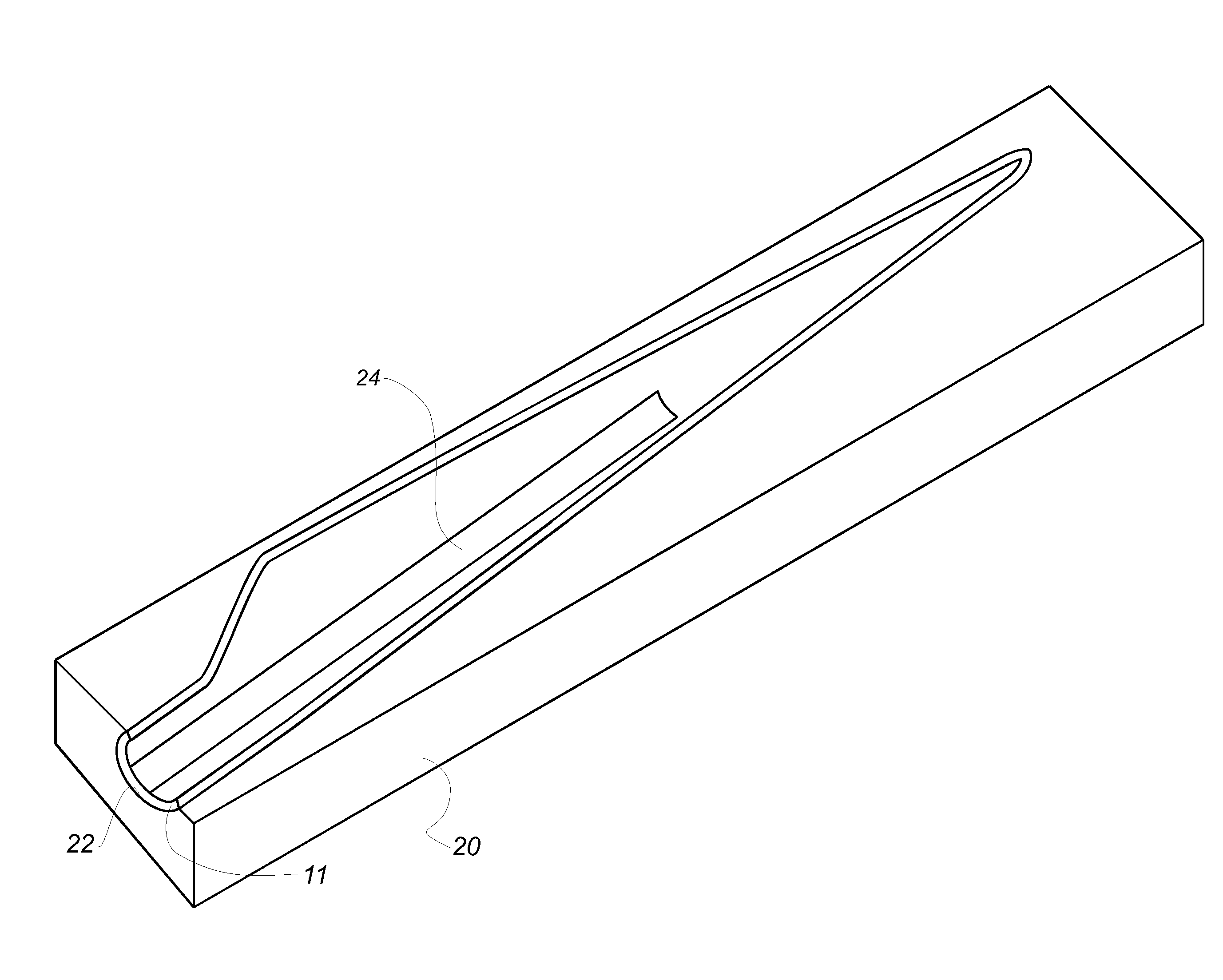
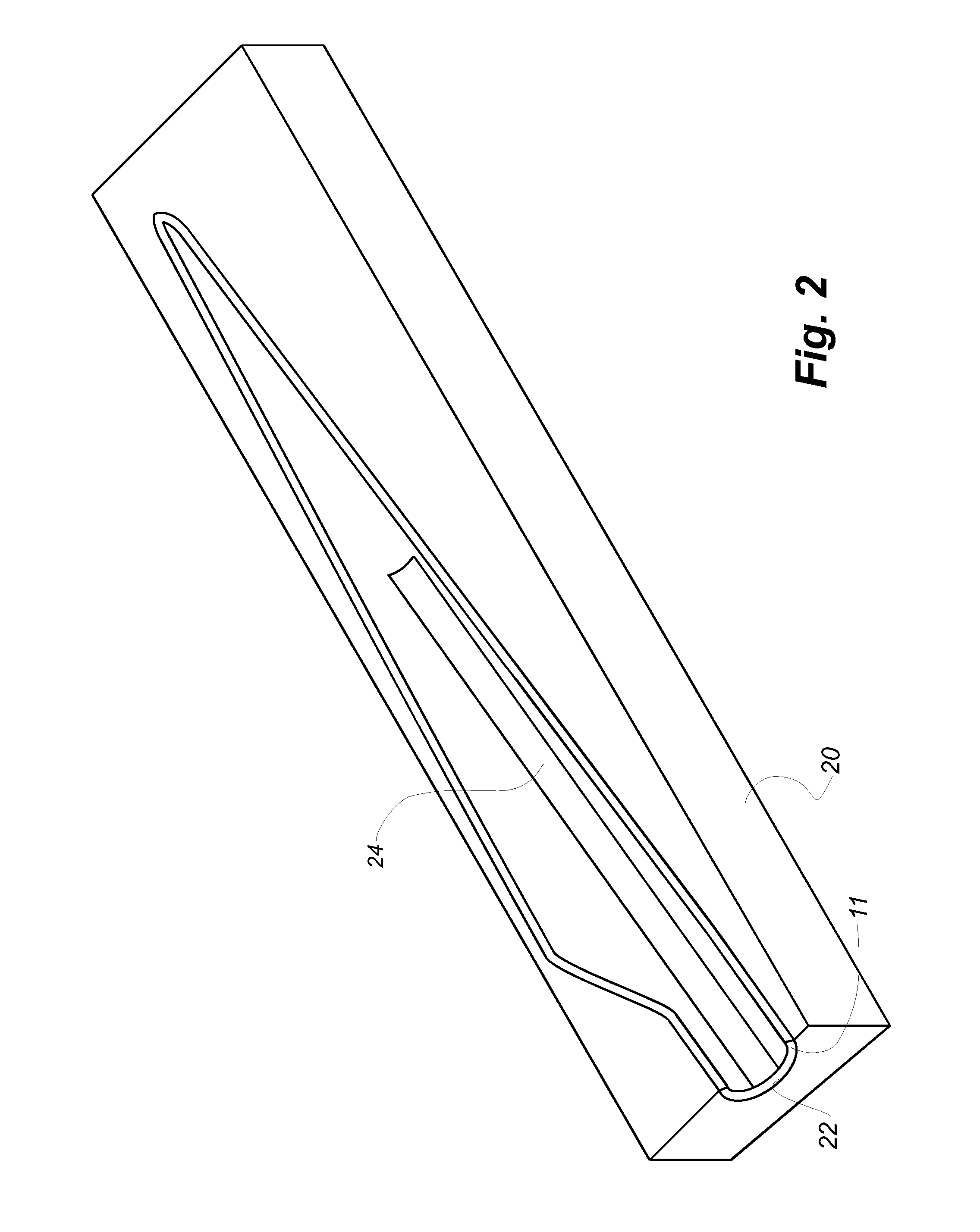
[0097]The wind turbine blades 10 are manufactured as fibre-reinforced composite structures comprising a fibre-reinforcement material embedded in a polymer matrix. The individual blades 10 comprise an aerodynamic shell, and the suction side and the pressure side of the aerodynamic shell are often manufactured as separate parts in moulds 20 as shown in FIG. 2. The blade shell parts 11 are manufactured separately by arranging the fibre-reinforcement material and typically also sandwich core material, such as foamed polymer or balsawood, on a mould surface 22 of the mould. The fibre reinforcem...


PUM

PropertyMeasurementUnit
widthaaaaaaaaaa
lengthaaaaaaaaaa
widthaaaaaaaaaa

Abstract

A method of manufacturing a wind turbine blade shell part is described. Fibre mats and a root end insert are laid up in a mould part in a layup procedure by use of an automated layup system. The fibre mats are laid up by use of a buffer so that the fibre mats may continuously be laid up on the mould surface, also during a cutting procedure. The root end insert is prepared in advance and mounted on a mounting plate. The root end insert is lowered onto the mould by use of the mounting plate and a lowering mechanism. After the wind turbine blade shell has been moulded, the mounting plate is removed.

Description

TECHNICAL FIELD[0001]The present invention relates to a system for automated layup of fibre mats and a method of laying up fibre mats for the manufacture of parts for a wind turbine blade, in particular the aerodynamic shell part of a wind turbine blade. The present invention further relates to a method of manufacturing a wind turbine blade shell part made of a composite structure comprising a fibre-reinforcement material embedded in a polymer matrix. The present invention additionally relates to a root end assembly for use in the method for manufacturing the wind turbine blade shell. Finally, the invention also relates to a mould for manufacturing a wind turbine blade shell part.BACKGROUND[0002]Wind turbine blades of fibre-reinforced polymer and in particular the aerodynamic shells of wind turbine blades are usually manufactured in moulds, where the pressure side and the suction side of the blade are manufactured separately by arranging glass fibre mats in each of the two mould par...

Claims


Application Information

Patent Timeline
Patent Type & Authority Applications(United States)
IPC IPC(8): B29C70/86B29C70/54B29C70/38
CPCB29C70/86B29C70/386B29K2105/0881B29L2031/085B29C70/545B29C33/12B29C70/388B29D99/0025F03D1/0658F05B2230/00B29C2793/0027Y02E10/72Y02P70/50B29C70/543B32B38/185B32B38/0004B29C70/56F05B2280/6003B29C65/7802
Inventor BORSTING, DENNIS ANDREMORTENSEN, IVAN ENGMARKFUGLSANG, LARSCHRISTIANSEN, PER KJAER
Owner LM WP PATENT HLDG
Why Eureka
Try Eureka