Active airpath bypass system

a bypass system and air path technology, applied in the field of intake system, can solve the problems of increasing the likelihood of engine misfire and combustion instability, and the inability to incorporate such bypass passages into the integrated cac system described above, and defeating the purpose of reducing engine packaging space, reducing engine emissions, and increasing the pressure in the combustion chamber

Active Publication Date: 2016-06-23
FORD GLOBAL TECH LLC
View PDF7 Cites 14 Cited by
  • Summary
  • Abstract
  • Description
  • Claims
  • Application Information

AI Technical Summary

Benefits of technology

[0002]Many engines utilize compressors in the intake system to provide boost to the engine to increase the pressure in the combustion chamber, thereby increasing the power output of the engine. Some engines also utilize an exhaust gas recirculation (EGR) loop to reduce emission from the engine and / or improve fuel economy. The EGR loop can be either “high pressure” (HP) where the EGR is taken before the turbine and injected after the compressor, or “low pressure” (LP) where the EGR is taken after the turbine and injected before the compressor. For both scenarios, the compressor and the EGR loop increase the temperature of the intake air provided to the cylinders, thereby reducing the density of the air provided to the cylinder. As a result, the combustion efficiency is decreased. To decrease the temperature of the intake air charge air coolers may be positioned in the intake system. In some engines, the charge air cooler may be positioned in a conduit downstream of the compressor and upstream of a throttle as part of the front end cooling module as the charge air cooler is typically air cooled. In other applications, the charge air cooler may be water cooled and mounted in the engine compartment. Recently, advances have been made to incorporate the charge air cooler into the intake system. For example, US 2013 / 0220289 discloses an intake system including a plenum and throttle body with a charge air cooler integrated within the plenum. The integration of the charger air cooler into the intake system enables the overall compactness of the intake system to be increased while providing charge air cooling to intake air. Further, US 2012 / 0285423 discloses an integrated charge air cooler intake system which includes static seals to ensure the effectiveness of the charge air cooler.

Problems solved by technology

When torque is increased, such as during acceleration, increased mass air flow may strip the condensate from the CAC, drawing it into the engine and increasing the likelihood of engine misfire and combustion instability.
However, the inventors herein have recognized potential issues with such methods.
Specifically, it may not be possible to incorporate such bypass passages into the integrated CAC system described above.
For example, adding a bypass passage may require extra tubing and valves outside of the integrated CAC and intake plenum, thereby defeating the purpose of an integrated CAC that reduces engine packaging space.

Method used


Image

  • Active airpath bypass system
  • Active airpath bypass system
  • Active airpath bypass system

Examples


Embodiment Construction

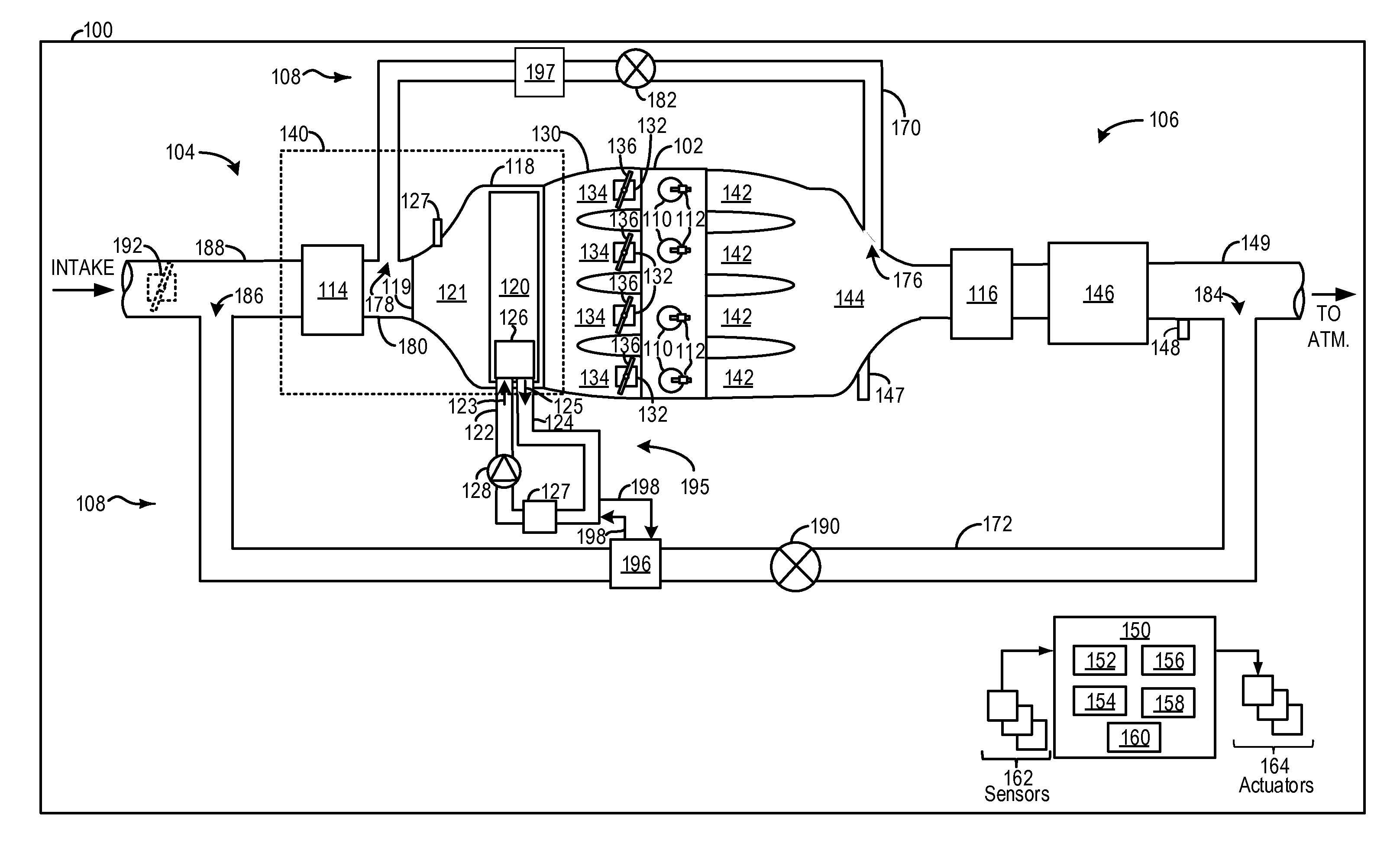
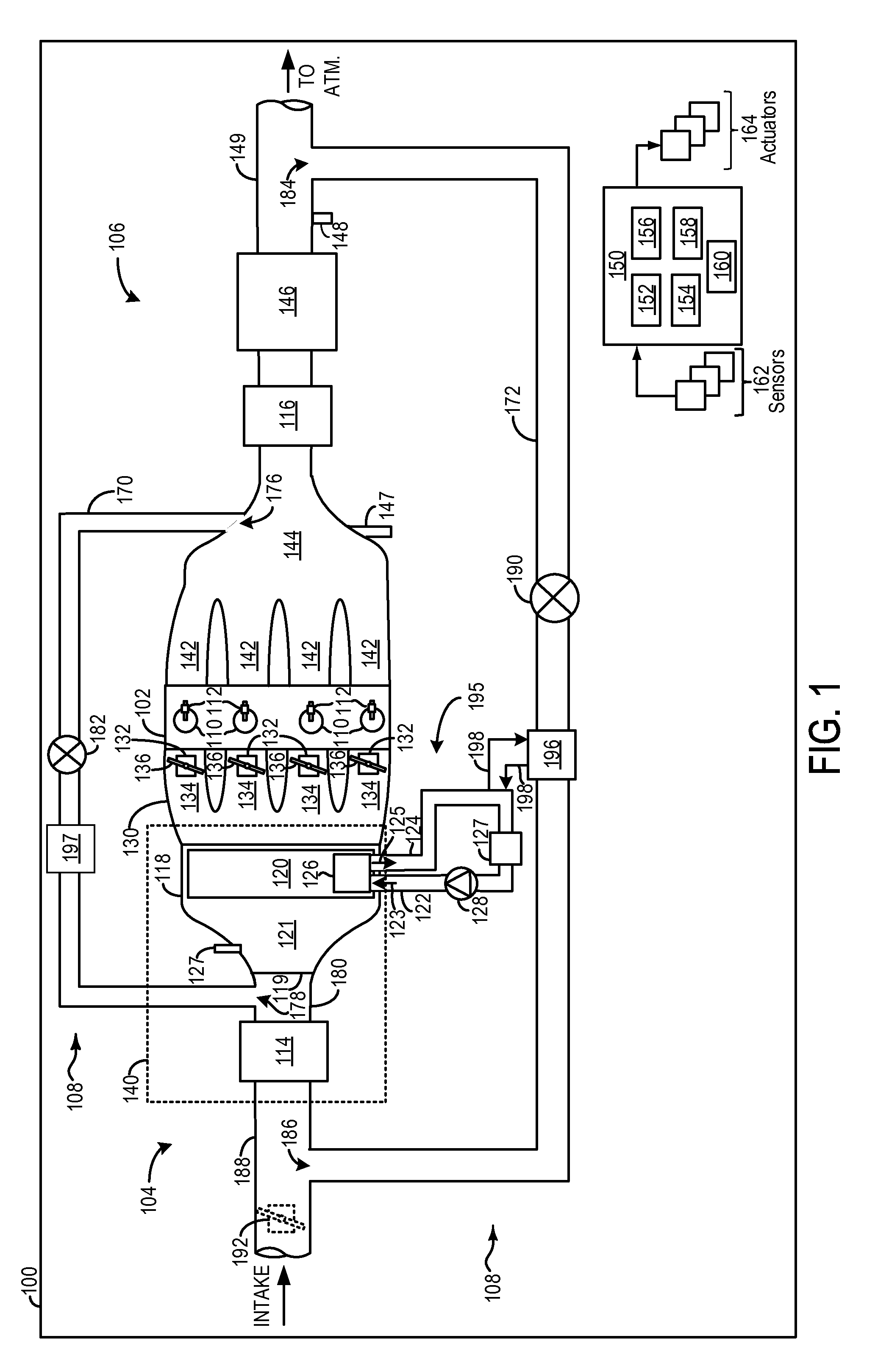
[0010]The following description relates to systems and method for adjusting the flow of intake air through a charge air cooler integrated into a plenum of an intake assembly. In a turbocharged engine as shown in FIG. 1, a compressor may be used to compress intake air and provide the engine with more power. However, compressing the intake air may raise the temperature of the intake air. Increased intake air temperature may result in engine knock and cause damage to the engine. A charge air cooler may be used to cool air before entering engine cylinders. In some cases the charge air cooler may be integrated into a plenum of the intake assembly which may have the benefits of reducing packaging size and increasing fuel economy. However, it may not always be desirable to flow intake air through the charge air cooler. In some cases, if the temperature of the intake air is low enough, condensate may form in the charge air cooler when the air is forced through it. The condensate may then be...


PUM


Abstract

Methods and systems are provided for regulating airflow through a charge air cooler integrated in an intake assembly. In one example, an engine intake assembly comprises a plenum having an integrated charge air cooler (CAC), a first header seal positioned around a circumference of a first CAC header, and a first rotatably movable seal positioned in a bypass passage of the plenum. The first movable seal interfaces via sliding contact with the first header seal and adjusting a position of the first movable seal may vary the amount of airflow through the bypass passage.

Description

FIELD[0001]The present application relates to an intake system with an integrated charge air cooler.BACKGROUND / SUMMARY[0002]Many engines utilize compressors in the intake system to provide boost to the engine to increase the pressure in the combustion chamber, thereby increasing the power output of the engine. Some engines also utilize an exhaust gas recirculation (EGR) loop to reduce emission from the engine and / or improve fuel economy. The EGR loop can be either “high pressure” (HP) where the EGR is taken before the turbine and injected after the compressor, or “low pressure” (LP) where the EGR is taken after the turbine and injected before the compressor. For both scenarios, the compressor and the EGR loop increase the temperature of the intake air provided to the cylinders, thereby reducing the density of the air provided to the cylinder. As a result, the combustion efficiency is decreased. To decrease the temperature of the intake air charge air coolers may be positioned in the...

Claims


Application Information

Patent Timeline
Patent Type & Authority Applications(United States)
IPC IPC(8): F02M25/07
CPCF02M25/0728F02B29/045F02B37/16F02B37/162F02B29/0462F02B29/0475F02M35/10026F02M35/10052F02M35/10268F02M26/05F02M26/06F02M26/23F02M26/28Y02T10/12F02B29/04F02M31/20F02M35/10
Inventor WICKS, CHRISTOPHER DONALD
Owner FORD GLOBAL TECH LLC
Why Eureka
Try Eureka