Dynamic lane management for interference mitigation

a technology of interference mitigation and dynamic lane management, applied in the field of electromagnetic interference, can solve the problems of exacerbated emi effects, degrade the performance of other circuitry within mobile computing devices, etc., and achieve the effects of reducing the emi experienced by the victim

Inactive Publication Date: 2016-06-23
QUALCOMM INC
View PDF1 Cites 5 Cited by
  • Summary
  • Abstract
  • Description
  • Claims
  • Application Information

AI Technical Summary

Benefits of technology

[0009]In another exemplary aspect, a method for mitigating EMI experienced by a victim receiver as a result of an aggressor communications bus is disclosed. The method comprises receiving information from a coexistence manager, wherein the information is related to EMI of a victim receiver as a result of an aggressor communications bus. The method further comprises assigning one or more application processor signals to be transmitted to the aggressor communications bus to one or more lanes associated with an interface to mitigate the EMI experienced by the victim receiver and allow the victim receiver to operate at or above an acceptable performance level. The method further comprises instructing a transceiver to assign one or more transceiver signals to be transmitted to the aggressor communications bus to the one or more lanes associated with the interface to mitigate the EMI experienced by the victim receiver and allow the victim receiver to operate at or above the acceptable performance level.
[0010]In another exemplary aspect, a transceiver is disclosed. The transceiver comprises an interface. The interface is configured to couple to an aggressor communications bus. The interface is further configured to transmit one or more transceiv...

Problems solved by technology

This increase in electromagnetic emissions causes electromagnetic interference (EMI) that degrades the performance of other circuitry within the mobile co...

Method used


Image

  • Dynamic lane management for interference mitigation
  • Dynamic lane management for interference mitigation
  • Dynamic lane management for interference mitigation

Examples


Embodiment Construction

[0018]With reference now to the drawing figures, several exemplary aspects of the present disclosure are described. The word “exemplary” is used herein to mean “serving as an example, instance, or illustration.” Any aspect described herein as “exemplary” is not necessarily to be construed as preferred or advantageous over other aspects.

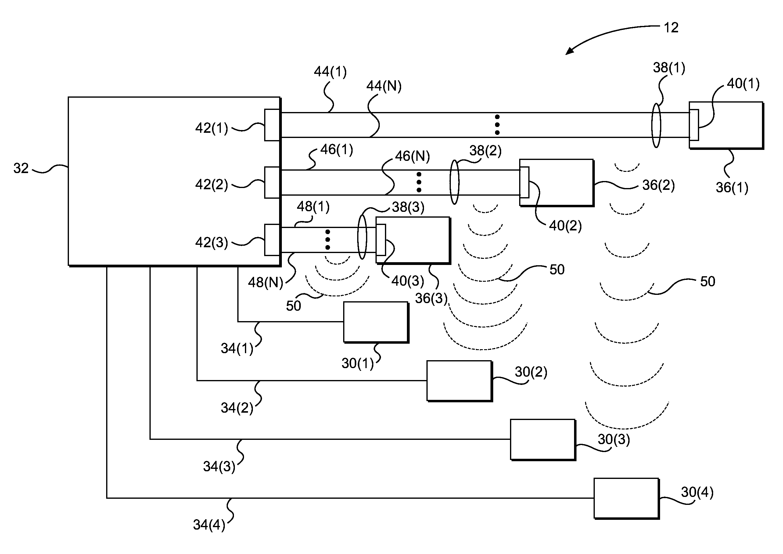
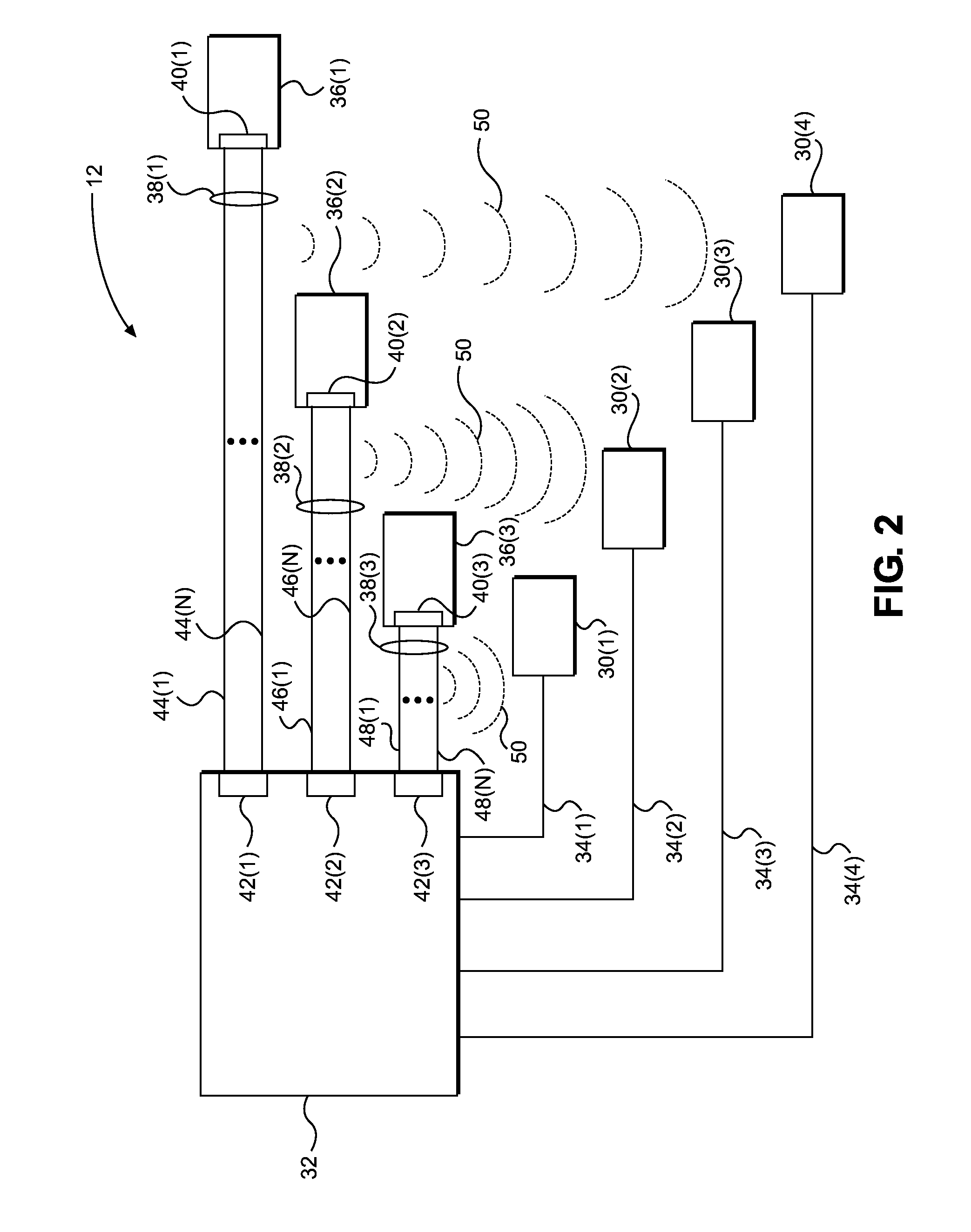
[0019]Aspects disclosed in the detailed description include dynamic lane management for interference mitigation. In one aspect, an integrated circuit (IC) is provided that employs a control system configured to mitigate electromagnetic interference (EMI) caused by an aggressor communications bus. The control system is configured to receive information related to EMI conditions and adjust which lanes of the aggressor communications bus are employed for signal transmission. In this manner, the IC includes an interface configured to couple to the aggressor communications bus. The interface is configured to transmit signals to and receive signals from the...


PUM


Abstract

Dynamic lane management for interference mitigation is disclosed. In one aspect, an integrated circuit (IC) is provided that employs a control system configured to mitigate electromagnetic interference (EMI) caused by an aggressor communications bus. The control system is configured to receive information related to EMI conditions and adjust which lanes of the aggressor communications bus are employed for signal transmission. The IC includes an interface configured to couple to the aggressor communications bus. The interface is configured to transmit signals to and receive signals from the aggressor communications bus. The control system is configured to use the information related to the EMI conditions to assign signals to be transmitted via particular lanes of the aggressor communications bus to mitigate the EMI experienced by a victim receiver. The control system provides designers with an additional tool that may reduce the performance degradation of the victim receiver attributable to EMI.

Description

BACKGROUND[0001]I. Field of the Disclosure[0002]The technology of the disclosure relates generally to electromagnetic interference (EMI), and particularly to mitigating effects of such EMI.[0003]II. Background[0004]Mobile computing devices, such as mobile phones and computer tablets, have become increasingly prevalent in contemporary society. These mobile computing devices commonly include multiple circuits that must operate concurrently for successful use of everyday functions. For example, a mobile computing device may be used to make phone calls or send e-mail messages via a wireless modem. The same mobile computing device may also perform other functions using other function-specific circuits, such as taking pictures with an integrated camera or viewing a video on an integrated display.[0005]In this regard, each circuit communicates with a central processor configured to execute instructions related to such functions. More specifically, data and clock signals are exchanged betwe...

Claims


Application Information

Patent Timeline
IPC IPC(8): G06F13/42G06F13/40
CPCG06F13/4221G06F13/4295G06F13/4022G06F13/409G06F13/4282G06F15/163H04B15/02H04L12/40169
Inventor WIETFELDT, RICHARD DOMINIC
Owner QUALCOMM INC
Why Eureka
Try Eureka