Removal of dust in urea finishing

Active Publication Date: 2016-06-30
STAMICARBON BV
View PDF7 Cites 21 Cited by
  • Summary
  • Abstract
  • Description
  • Claims
  • Application Information

AI Technical Summary

Benefits of technology

[0019]In order to better address one or more of the foregoing desires, the invention, in one aspect, presents a method for the removal of urea dust from the off-gas of a finishing section of a urea production plant, the method co

Problems solved by technology

These drawbacks led to the development of the fluidized bed granulation technique, where the urea melt is sprayed on granules that grow in size as the process continues.
In addition, the operating costs of running pollution control equipment can be substantial, and so there is also a constant demand for more efficient technologies.
The removal of urea dust is challenging per se, since the amounts of off-gas (mainly air) are enormous, whilst the concentration of urea dust is low.
A further problem is that the large amounts of air needed in urea finishing, results in this part of the production process being a relatively costly effort due to the need for very large extractor fans having a large electricity consumption.
Particularly, when the air is subjected to scrubbing in order to reduce the emission of urea dust, and specifically a major part of

Method used


Image

  • Removal of dust in urea finishing
  • Removal of dust in urea finishing

Examples


example

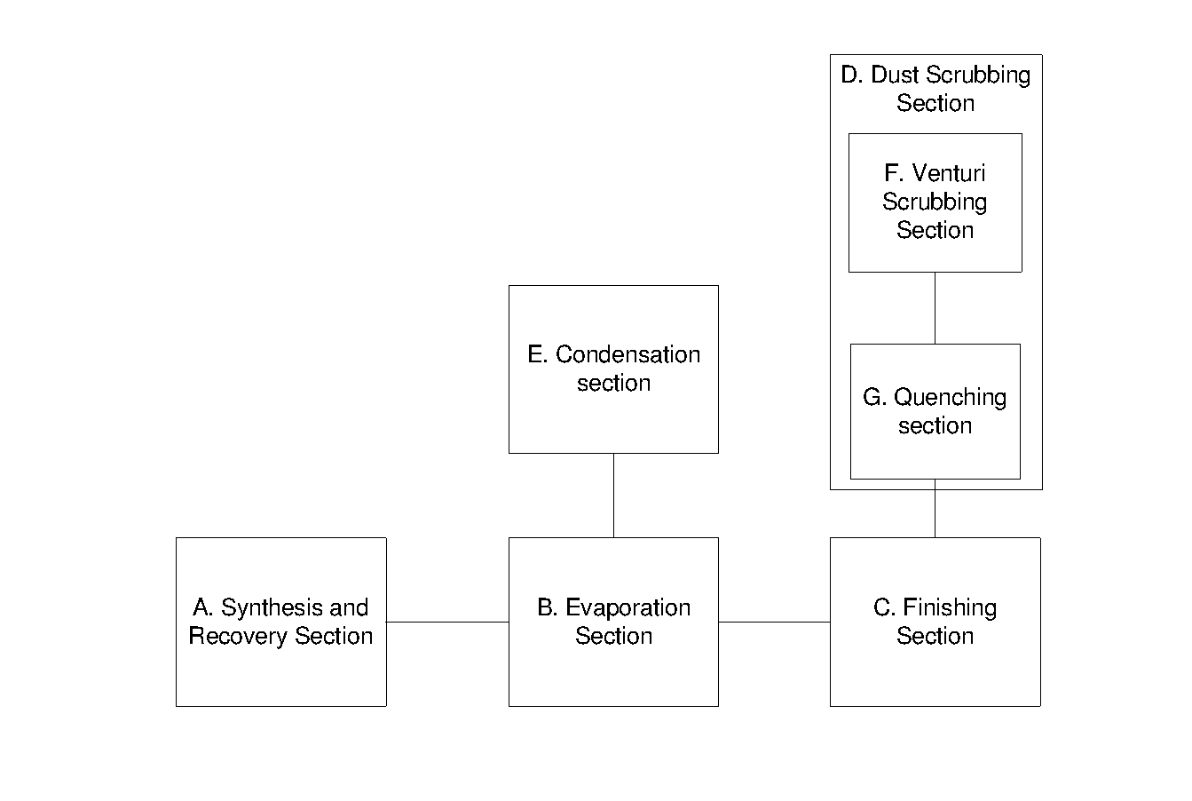
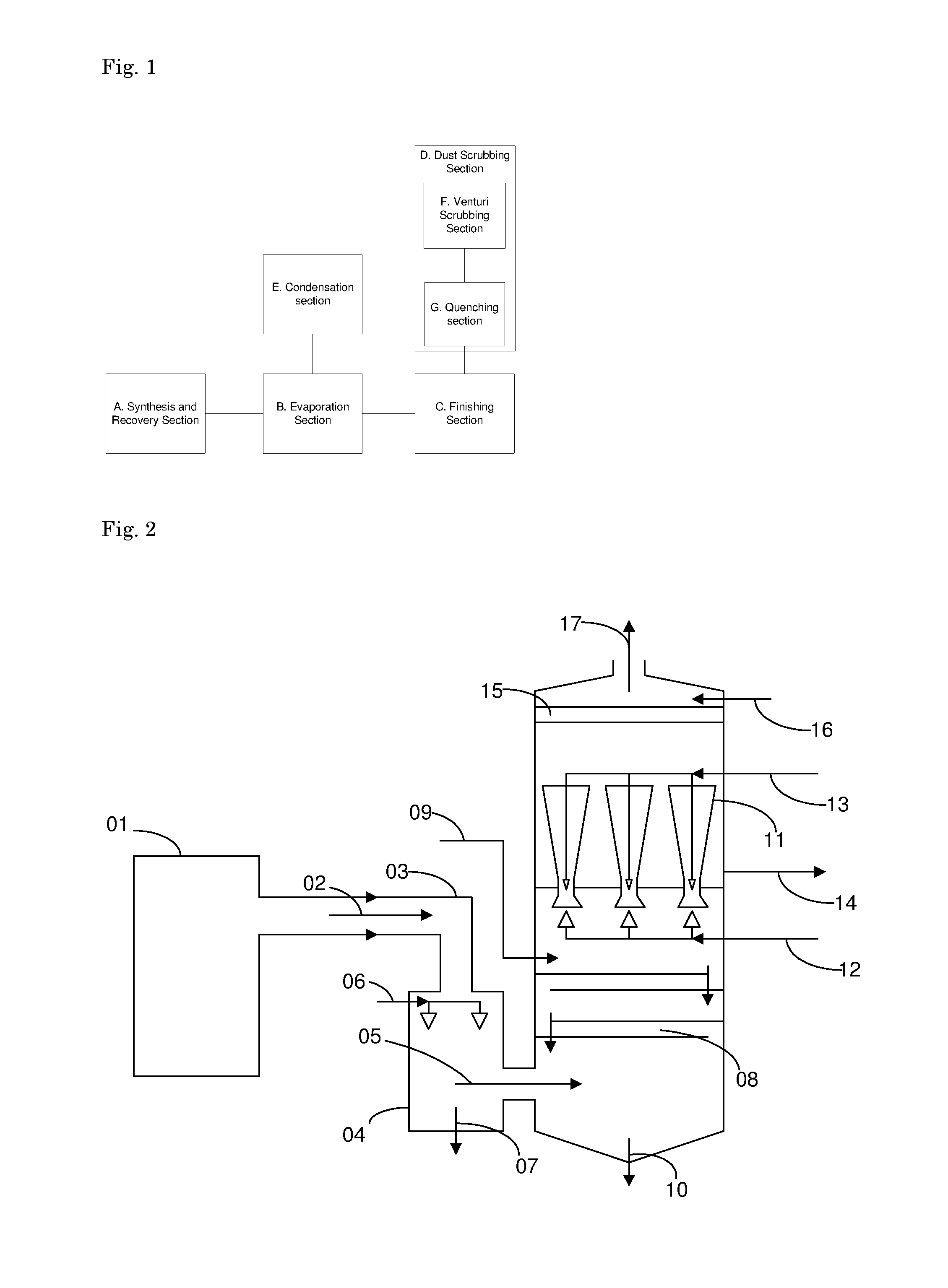
[0078]This Example refers to FIG. 2, which shows an exemplary dust scrubbing system of the present invention. An off-gas stream laden with entrained urea dust-particles is generated by a finishing section (01). From the finishing section (01), the off-gas stream (02) is delivered to the dust-scrubbing system though a duct (03).

[0079]The dust scrubbing system removes urea particles from the off-gas stream 02 in two stages. In a first scrubbing stage, the so-called quenching stage, the off-gas 02 flows though the quenching section 04, where the majority of large urea particles are removed from the off-gas, resulting in a partially scrubbed off-gas flow effluent as flow 05.

[0080]Furthermore in the quenching section 04, the off-gas 02 is cooled and moistened with water. It is preferred that the gas in flow 05 is near to moisture saturation.

[0081]For the purposes of cooling, saturating and scrubbing, a liquid flow 06 is introduced through nozzles in the quenching section 04. The liquid f...


PUM

PropertyMeasurementUnit
Temperatureaaaaaaaaaa

Abstract

Disclosed is a method for the removal of urea dust from the off- gas of a finishing section (1) of a urea production plant, the method comprises subjecting the off-gas to quenching with water (06) so as to produce quenched off-gas, and subjecting the quenched off-gas to scrubbing using at least one venturi scrubber (11). As a result, a lower pressure drop over the scrubber is attained, and a more efficient growth of urea particles, facilitating the removal thereof.

Description

[0001]The invention is in the field of urea production, and pertains to the removal of urea dust from the off-gas associated with the production of solid urea particles (urea finishing). Particularly, the invention pertains to the reduction of the emission of urea dust occurring from such a urea plant finishing section. The invention also pertains to a urea production plant, and to revamping an existing urea production plant.BACKGROUND OF THE INVENTION[0002]Urea is produced from ammonia and carbon dioxide. Today's urea production involves relatively clean processes, particularly low in the emission of urea dust and ammonia. However, besides the chemical synthesis of urea, the production of urea on a commercial scale requires that the urea be presented in a suitable solid, particulate form. To this end, urea production involves a finishing step in which a urea melt is brought into the desired particulate form, generally involving any one of prilling, granulation, and pelletizing.[000...

Claims


Application Information

Patent Timeline
IPC IPC(8): B01D47/10
CPCB01D47/10B01D53/58B01D53/78B01J2/16C07C273/16B01D47/06C07C273/02Y02P20/50
Inventor SOONS, PETRUS CATHARINA GERLACHDIRKX, WILFRIED MARC RENAAT
Owner STAMICARBON BV
Why Eureka
Try Eureka