Load following single bed reversing blower adsorption air separation system

a technology of adsorption air and adsorption bed, which is applied in the direction of separation process, dispersed particle separation, chemical apparatus and processes, etc., can solve the problems of poor process turndown ratio, lack of additional adsorption bed, and limited turndown of dual blower system, so as to increase flow rate and reduce the flow rate , the effect of reducing the flow ra

Active Publication Date: 2016-06-30
PACIFIC CONSOL INDS
View PDF9 Cites 0 Cited by
  • Summary
  • Abstract
  • Description
  • Claims
  • Application Information

AI Technical Summary

Benefits of technology

[0011]The presence of the buffer tank and the volume thereof ensures that rapidly increasing demand sensed at the second location can be responded to by the compressor and the compressor will not exhaust the supply within the buffer tank before the heightened demand is sensed and responded to at the first location within the buffer tank, causing the reversible blower to increase flow rate and produce oxygen more quickly. Correspondingly, if oxygen demand sensed by the pressure sensor at the second location decreases rapidly, causing the compressor to operate at a significantly lower flow rate, the buffer tank is sufficiently large that the reversible blower can continue at a high flow rate (for approximately a minute) to produce oxygen which can be stored up in the buffer tank, with such oversupply being readily absorbed within the buffer tank for the up to one minute time period that such a rapidly decreasing demand might cause, before the sensed increased pressure in the buffer tank causes a reduction in the flow rate of the reversible blower. Stable load following is thus achieved and efficient oxygen production is maintained even with a turned down ratio of fifty percent, seventy-five percent or more.
[0012]Accordingly, a primary object of the present invention is to provide a single bed reversing blower (SBRB) vacuum swing adsorption (VSA) or other adsorption based air separation unit which can flexibly meet demand over a wide range, by effectively matching O2 demand with flow rates within the air separation unit.
[0013]Another object of the present invention is to provide a single bed reversing blower air separation unit which maintains efficient operation even when O2 demand varies widely.
[0014]Another object of the present invention is to provide an SBRB VSA air separation unit which can maintain continuous operation at variable flow rates and avoid excessive start up and shut down cycles, while meeting variable O2 demand.
[0015]Another object of the present invention is to provide an air separation unit which operates in a manner following the load placed on the air separation unit with a high turn down ratio while still maintaining efficient O2 producing operation.
[0016]Another object of the present invention is to provide a method for controlling flow rates of equipment within an adsorption based air separation unit to efficiently respond to changes in O2 load.

Problems solved by technology

Although the single bed reversing blower (SBRB) VSA process is simple in practice, its simplicity comes with performance trade-offs when compared to multi-bed systems.
Firstly, the lack of additional adsorber beds does not allow for a crucial bed to bed equalization.
Another waste of power in any adsorption process is the poor turndown ratio of the process.
In a multi-bed, dual blower system turndown is limited by the fact that the blowers must remain powered up.
While not particularly efficient, the blowers are allowed to run unloaded, saving some power.

Method used


Image

  • Load following single bed reversing blower adsorption air separation system
  • Load following single bed reversing blower adsorption air separation system
  • Load following single bed reversing blower adsorption air separation system

Examples


Embodiment Construction

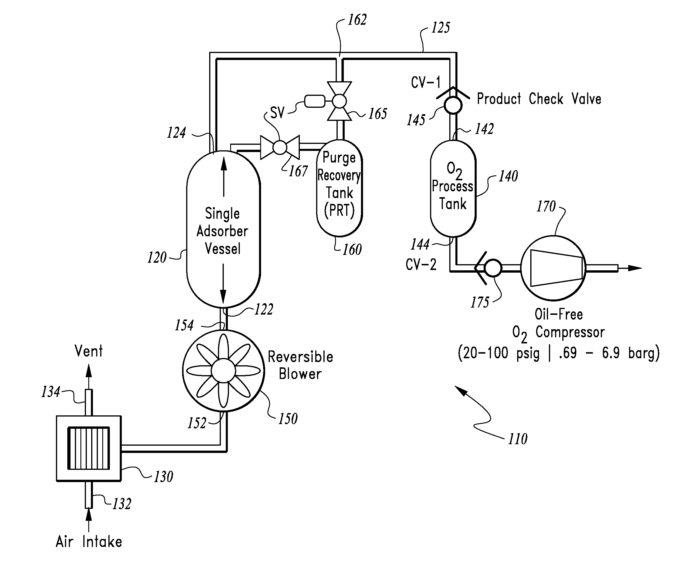
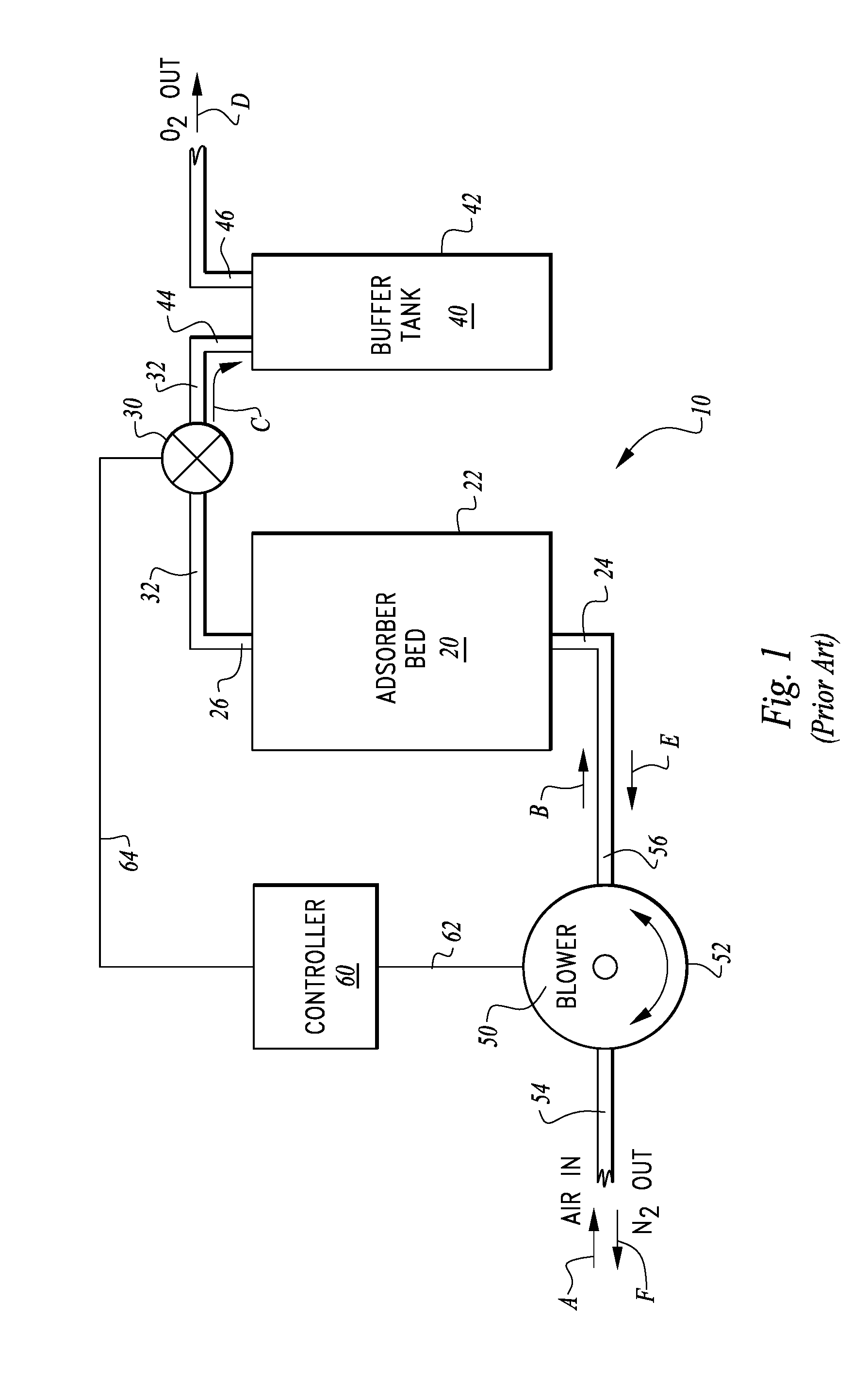
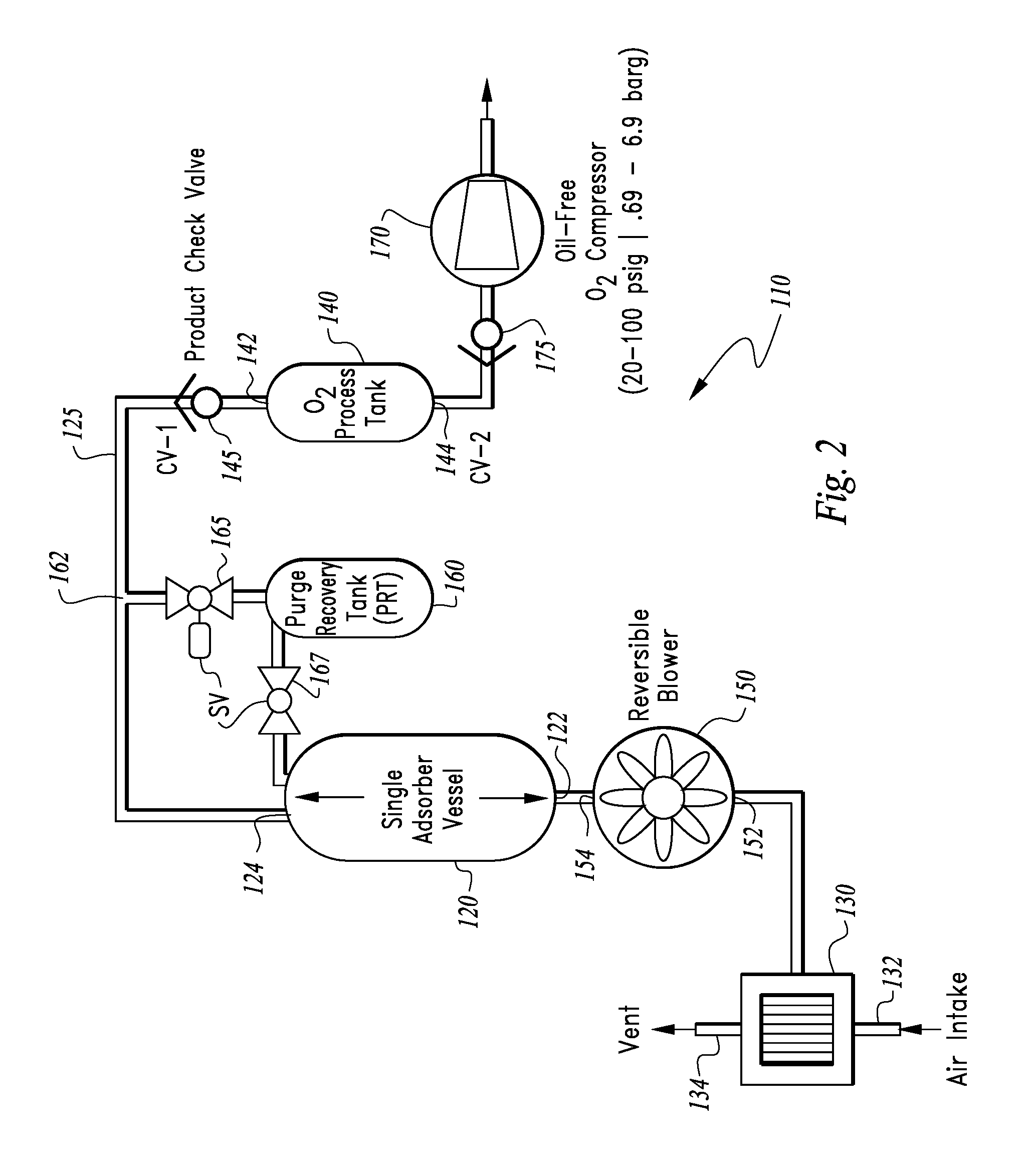
[0023]Referring to the drawings, wherein like reference numerals represent like parts throughout the various drawing figures, reference numeral 10 (FIG. 1) is directed to a prior art oxygen separator configured to separate / concentrate oxygen from air. This separator is modified by the air separation unit 110 of this invention (FIGS. 2-5) and the blower driving system 210 of this invention (FIG. 4), as explained in detail below.

[0024]In essence, and with particular reference to FIG. 1, basic details of the oxygen separator 10 modified by the air separation unit 110 and blower driving system 210 of this invention are disclosed. The oxygen separator 10 includes an adsorber bed 20 including an adsorber material therein which preferentially adsorbs nitrogen, CO2 and water over oxygen. A valve 30 is located downstream of the adsorber bed 20. A buffer tank 40 is provided downstream of the valve 30. A blower 50 defines a preferred form of pump located upstream of the adsorber bed 20. A cont...


PUM

PropertyMeasurementUnit
power consumption rateaaaaaaaaaa
power consumptionaaaaaaaaaa
power rateaaaaaaaaaa

Abstract

An exemplary single bed reversing blower adsorption based air separation unit is configured to follow the O2 load placed thereon by adjusting flow rates therethrough and power consumption. At least one and preferably multiple pressure sensors sense O2 pressure within an O2 storage region downstream of an adsorber vessel. These sensed pressures are utilized to generate control signals controlling flow rates at locations upstream of the compressor, such as at a reversible blower and an output compressor. Control loops for the blower and the compressor are independent of each other and have different time constants. Effective following of the O2 load is thus achieved without driving the air separation unit into operational conditions outside of design and also maintaining optimal power consumption for the O2 produced, such that efficiency is maintained over a large turndown ratio.

Description

CROSS-REFERENCE TO RELATED APPLICATIONS[0001]This application claims benefit under Title 35, United States Code §119(e) of U.S. Provisional Application No. 62 / 098,052 filed on Dec. 30, 2014.FIELD OF THE INVENTION[0002]The following invention relates to air separation units for separation of oxygen from air, such as utilizing a single bed reversing blower adsorption based air separation unit. More particularly, this invention relates to single bed reversing blower adsorption based air separation units which can have an oxygen supply therefrom efficiently adjusted to match an oxygen demand from the air separation unit.BACKGROUND OF THE INVENTION[0003]The production of oxygen using vacuum swing adsorption (VSA) is well-known to air separation technologists. VSA offers a simple non-cryogenic method to produce gaseous oxygen at purities of 80% to 95%. In the last 20 years oxygen VSA plants have become widespread and are offered in various bed configurations. The multi-bed VSA is typicall...

Claims


Application Information

Patent Timeline
Patent Type & Authority Applications(United States)
IPC IPC(8): B01D53/047
CPCB01D2259/40009B01D2259/401B01D53/0476B01D2257/40B01D2256/12B01D53/053B01D2257/102B01D2259/402B01D2259/40007B01D2257/80B01D53/002B01D53/02B01D53/22B01D53/229B01D63/02B01D2257/11
Inventor LOPEZ, JAVIERBURNS, JASONGOSHAY, WILLIAM K.NAHEIRI, TARIK
Owner PACIFIC CONSOL INDS
Why Eureka
Try Eureka