

Method of acylating an aromatic compound
a technology of aromatic compounds and acylating methods, which is applied in the field of acylating aromatic compounds, can solve the problems of very fast deactivation of catalysts, and achieve the effect of increasing the service time of catalysts
- Summary
- Abstract
- Description
- Claims
- Application Information
AI Technical Summary
Benefits of technology
Problems solved by technology
Method used
Image

Examples
example 1
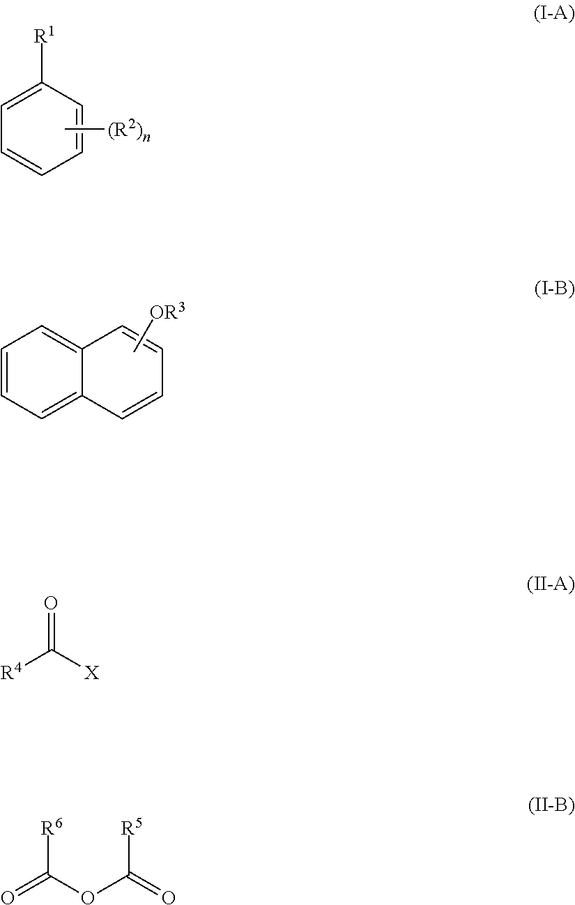
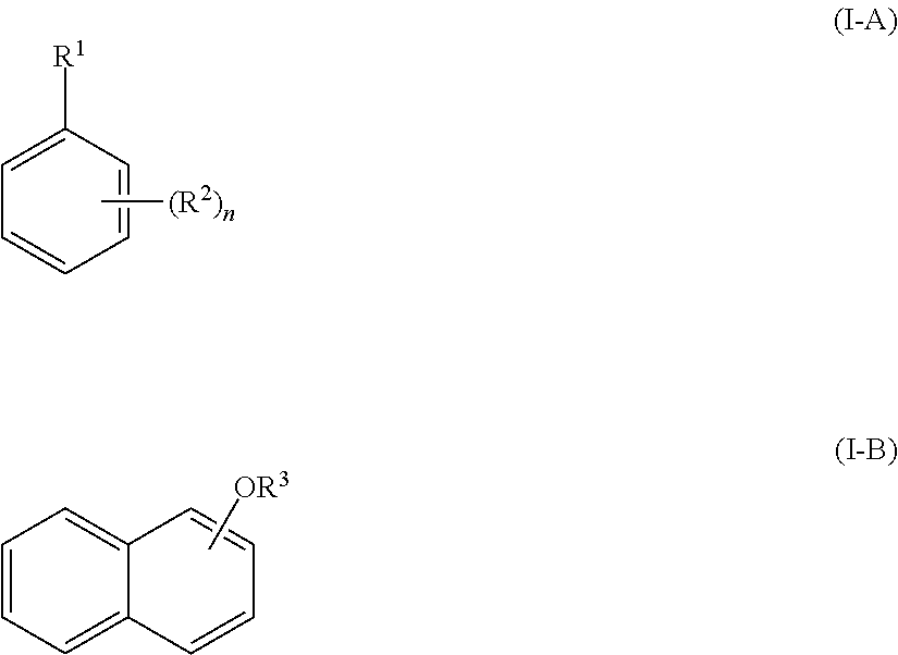
Acylation of Anisole in a Continuous Manner
[0094]The resin has been preconditioned during one hour by contacting it with the reaction mixture at room temperature.
[0095]13 mL of Amberlyst™ 16 WET (Dow Chemicals) have been added to a vertically oriented tubular fixed bed reactor equipped with a heating mantle. The fixed bed reactor was then heated up to a temperature of 110° C. A mixture of anisole and acetic anhydride in a molar ratio of anisole to acetic anhydride of 0.9 is introduced at the top of the reactor by means of a membrane pump to the reactor at a Weight Hourly Space Velocity (WHSV) of 0.2 per hour. The reaction mixture is removed continuously at the bottom of the reactor. Conversion and selectivity as defined above are determined by analysing samples by gas chromatography at reaction service times indicated in table 1.
TABLE 1Conversion, selectivity and yield of the acylation of anisole.Service time [h]Conversion [%]Selectivity [%]Yield [%]2229520.9100159514.3220149513.3
[0...
example 2
Acylation of Anisole in a Continuous Manner
[0099]The resin has been preconditioned during one hour by contacting it with the reaction mixture at room temperature.
[0100]400 mL of Amberlyst™ 16 WET (Dow Chemicals) have been added to a vertically oriented tubular fixed bed reactor equipped with a heating mantle. The fixed bed reactor was then heated up to a temperature of 110° C. A mixture of anisole and acetic anhydride in a molar ratio of anisole to acetic anhydride of 0.9 is introduced at the top of the reactor by means of a membrane pump to the reactor at a Weight Hourly Space Velocity (WHSV) of 0.02 per hour. The reaction mixture is removed continuously at the bottom of the reactor. Conversion and selectivity as defined above are determined by analysing samples by gas chromatography at reaction service times indicated in table 2.
TABLE 2Conversion, selectivity and yield of the acylation of anisole.Service time [h]Conversion [%]Selectivity [%]Yield [%]55239822.5457229420.7652229420....
example 3
Acylation of Anisole in a Continuous Manner (Comparison)
[0102]The resin has been preconditioned during one hour by contacting it with the reaction mixture at room temperature.
[0103]3 mL of Amberlyst™ 31 WET (Dow Chemicals), which is a gel-type and not a macroreticular (as in example 1 and 2) sulfonic acid exchange resin, have been added to a vertically oriented tubular fixed bed reactor equipped with a heating mantle. The fixed bed reactor was then heated up to a temperature of 110° C. A mixture of anisole and acetic anhydride in a molar ratio of anisole to acetic anhydride of 0.9 is introduced at the top of the reactor by means of a membrane pump to the reactor at a Weight Hourly Space Velocity (WHSV) of 5 per hour. The reaction mixture is removed continuously at the bottom of the reactor. Conversion and selectivity as defined above are determined by analysing samples by gas chromatography at reaction service times indicated in table 3.
TABLE 3Conversion, selectivity and yield of th...
PUM
| Property | Measurement | Unit |
|---|---|---|
| shrinkage | aaaaa | aaaaa |
| shrinkage | aaaaa | aaaaa |
| shrinkage | aaaaa | aaaaa |
Abstract
Description
Claims
Application Information