Magnetic resonance imaging apparatus and temperature information measurement method

a technology of magnetic resonance imaging and temperature information, which is applied in the field of magnetic resonance imaging technique, can solve the problems of degrading the accuracy of fitting and the decrepit accuracy of calculated temperature, and achieve the effect of improving the accuracy of temperature measurement in a living body

Inactive Publication Date: 2016-07-07
HITACHI LTD
View PDF7 Cites 17 Cited by
  • Summary
  • Abstract
  • Description
  • Claims
  • Application Information

AI Technical Summary

Benefits of technology

[0013]According to the present invention, in the temperature measurement using MRS / MRSI, accuracy of the measurement of temperature in a living body is improved.

Problems solved by technology

Since the resonant frequencies of the substances are obtained by fitting to a model function, if the shape of the measured spectral peak is distorted, fitting accuracy is degraded, and accuracy of the calculated temperature is also degraded.

Method used


Image

  • Magnetic resonance imaging apparatus and temperature information measurement method
  • Magnetic resonance imaging apparatus and temperature information measurement method
  • Magnetic resonance imaging apparatus and temperature information measurement method

Examples


first embodiment

[0029]Hereafter, embodiments of the present invention will be explained. In all the appended drawings for explaining the embodiments referred to below, the same numerical symbols are assigned to elements having the same function, and repetitive explanations thereof will be omitted.

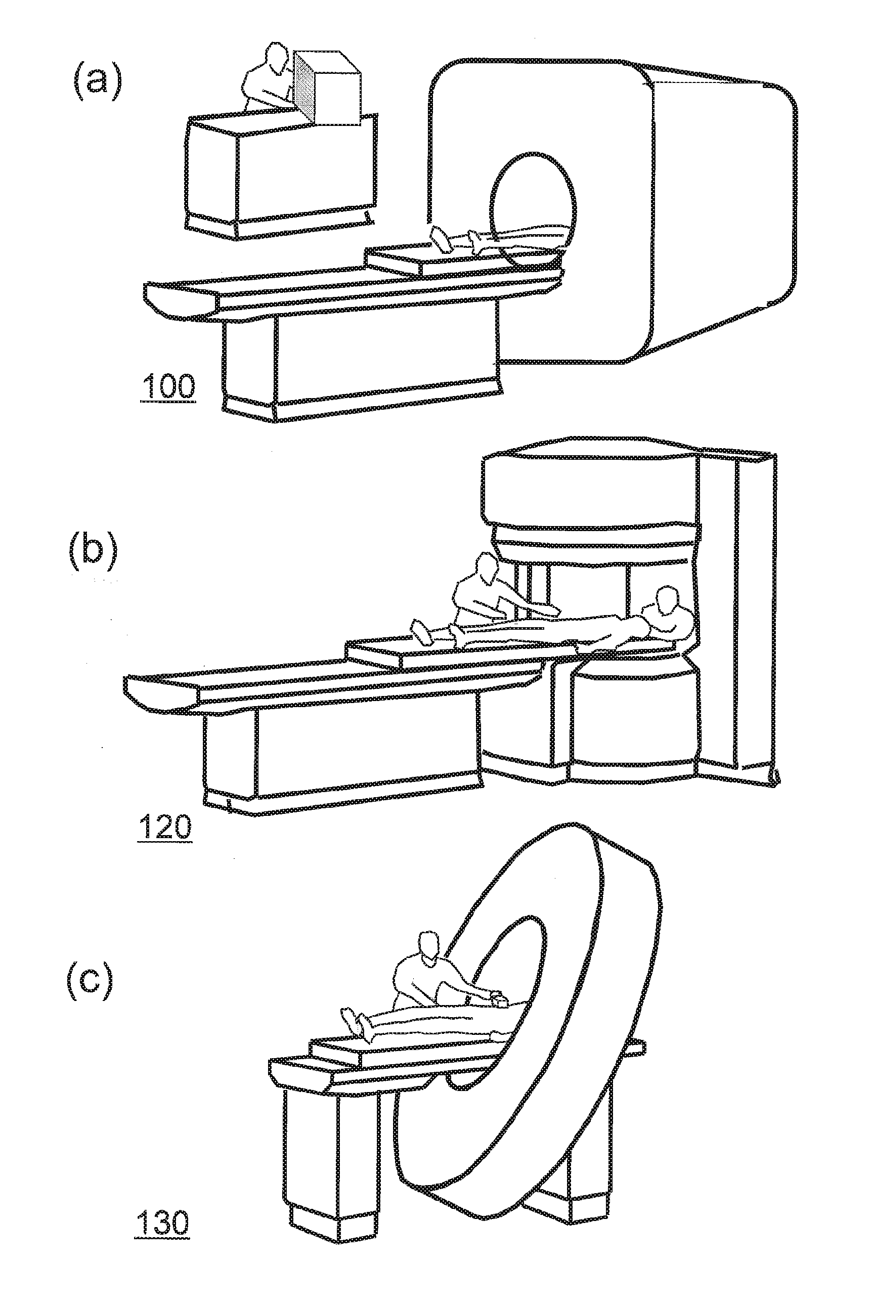
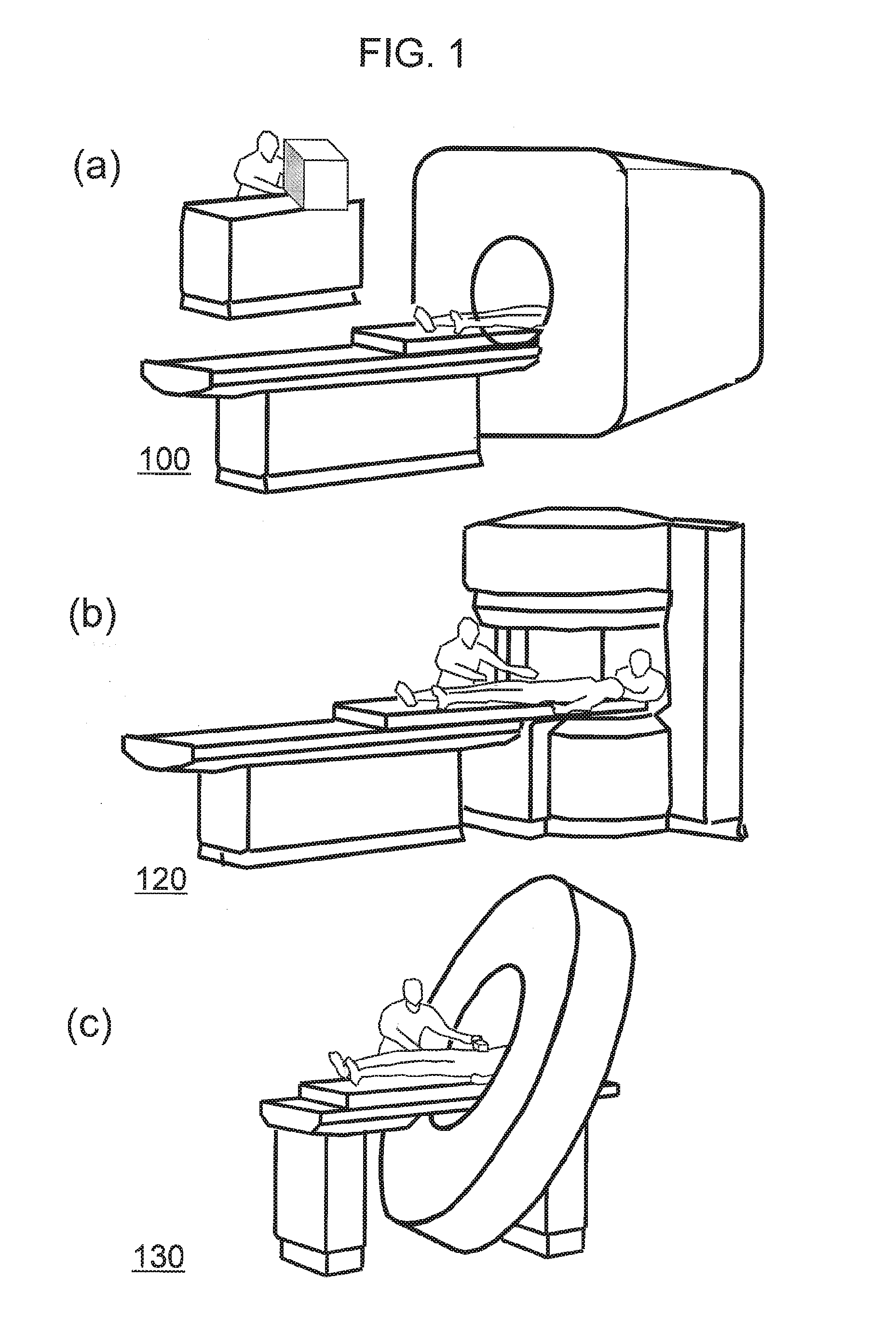
[0030]First, the magnetic resonance imaging apparatus (MRI apparatus) of this embodiment will be explained. FIGS. 1, (a) to (c) are exterior views of the MRI apparatuses of this embodiment. FIG. 1, (a) shows an MRI apparatus 100 of the horizontal magnetic field type using a tunnel-shaped magnet that generates a static magnetic field with a solenoid coil. FIG. 1, (b) shows a hamburger type (open type) MRI apparatus 120 of the vertical magnetic field type, which comprises separate upper and lower magnets for enhancing spaciousness. FIG. 1, (c) shows an MRI apparatus 130 using a tunnel-shaped magnet similar to that shown in FIG. 1, (a), in which the magnet has a shorter depth and is leaned in order to enhance...

second embodiment

[0111]Hereafter, the second embodiment of the present invention will be explained. According to the first embodiment, signals of cerebrospinal fluid are suppressed by applying the frequency-selective pulse that acts only on nuclear magnetization of water, and the diffusion-weighted gradient magnetic field pulse as pre-pulses. In contrast, in this embodiment, a plurality of frequency-selective CHESS pulses are irradiated as pre-pulses to suppress signals of cerebrospinal fluid.

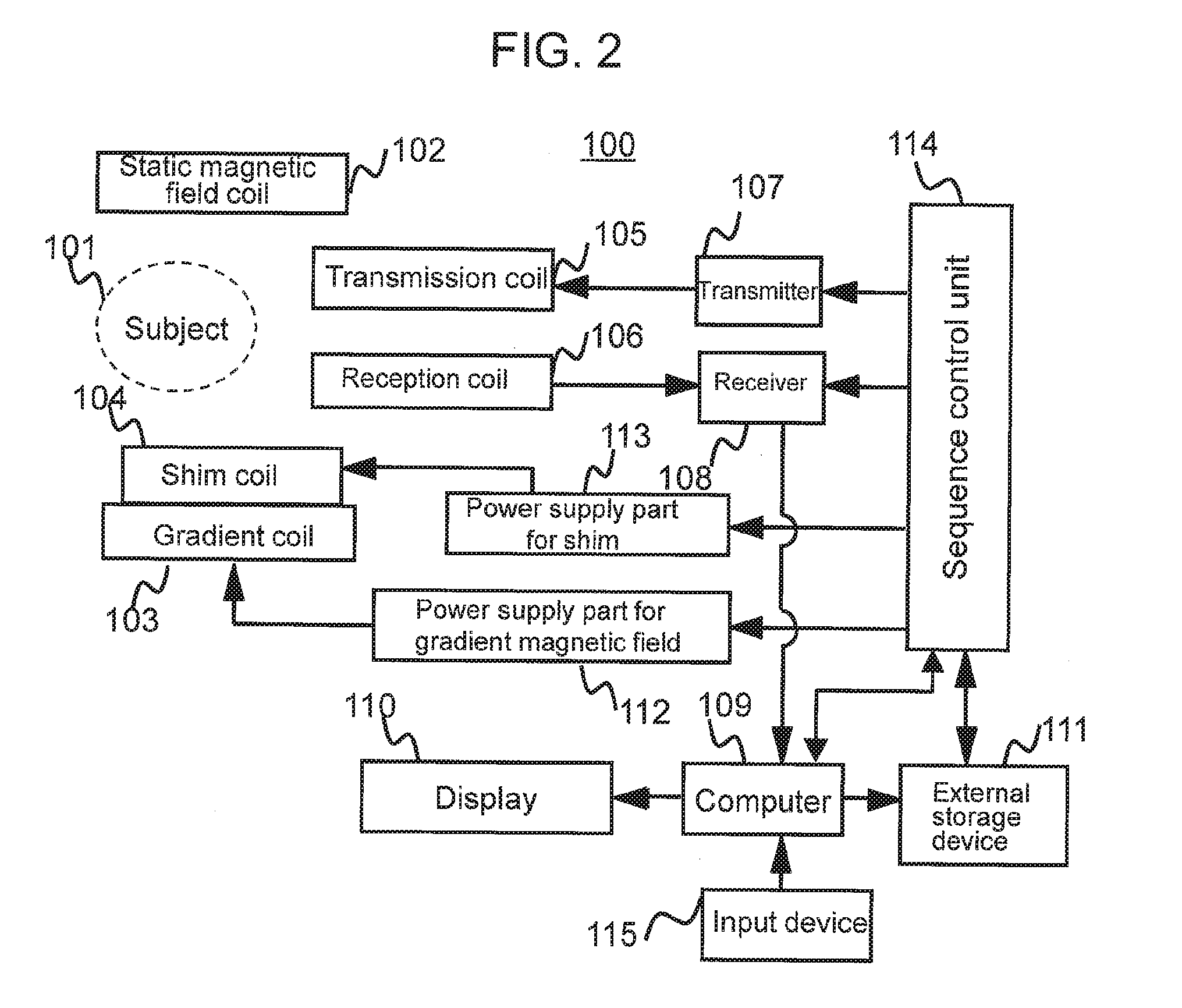
[0112]The MRI apparatus 100 of this embodiment has basically the same configuration as that of the first embodiment. The functional configuration realized by the computer 109 is also the same. However, the pre-pulses applied for suppressing signals of cerebrospinal fluid differ as described above. Therefore, the cerebrospinal fluid suppression sequence is different. Hereafter, explanation of this embodiment will be made with being focused on the configuration different from that of the first embodiment.

[0113]Ac...


PUM


Abstract

A technique for improving accuracy of temperature measurement in a living body using MRS / MRSI is provided. A cerebrospinal fluid suppression sequence that does not affect nuclear magnetic resonance signals of metabolite, but suppresses nuclear magnetic resonance signals of cerebrospinal fluid is executed in advance of execution of a signal measurement sequence for measuring nuclear magnetic resonance signals of water and a desired metabolite. There are thereby obtained spectra of water and the metabolite obtained from the nuclear magnetic resonance signals of water and the metabolite in which nuclear magnetic resonance signals of cerebrospinal fluid is suppressed. The obtained spectral peaks are fitted to a model function to obtain resonant frequencies of water and the metabolite, and the difference thereof is used to calculate temperature.

Description

TECHNICAL FIELD[0001]The present invention relates to a magnetic resonance imaging technique, especially techniques of magnetic resonance spectroscopy (MRS) and magnetic resonance spectroscopic imaging (MRSI), in which types of molecules, components etc. in living bodies are examined by utilizing difference of resonant frequencies of substances.BACKGROUND ART[0002]Magnetic resonance imaging apparatuses are apparatuses that irradiate a radio frequency magnetic field of a specific frequency on a measurement object placed in a static magnetic field to induce a magnetic resonance phenomenon, and thereby obtain physical or chemical information of the measurement object. Magnetic resonance imaging (MRI) widely used today is a method of imaging difference of hydrogen nucleus density, relaxation time, or the like varying depending on types of biological tissues by mainly using the nuclear magnetic resonance phenomenon of hydrogen nucleus in water molecule. This technique enables imaging of ...

Claims


Application Information

Patent Timeline
Patent Type & Authority Applications(United States)
IPC IPC(8): A61B5/055A61B5/01A61B5/00
CPCA61B5/055A61B5/7257A61B5/01A61B5/0042A61B5/015A61B2576/026G01R33/4804G16H30/40
Inventor SHIRAI, TORUYOKOSAWA, SUGURUOCHI, HISAAKIBITO, YOSHITAKA
Owner HITACHI LTD
Why Eureka
Try Eureka