Isolation transformer, and x-ray generating apparatus and radiography system including the same
- Summary
- Abstract
- Description
- Claims
- Application Information
AI Technical Summary
Benefits of technology
Problems solved by technology
Method used
Image
Examples
example 2
[0053]An isolation transformer was manufactured similarly to Example 1 with the exception that, as illustrated in FIG. 5A to FIG. 5E, the separately manufactured partition structure 15 was fixed to the inner periphery of the first container 5. The partition structure 15 had a cylindrical shape having an outer diameter of 15 mm, a thickness of 1 mm, and a length of 40 mm. The cutout 15a each having a length of 10 mm and a width of 5 mm were formed in both ends of the partition structure 15 so that the secondary coil 7 was to be wound therearound. The partition structure 15 was formed of a PEEK resin through cutting work. Further, the partition structure 15 was not fixed to the first container 5 with an adhesive or the like, but was fixed thereto by being wound by the secondary coil 7 together with the first container 5 after the partition structure 15 and the first container 5 were aligned. The shortest distance between the primary coil 3 and the secondary coil 7 is lengthened by abo...
example 3
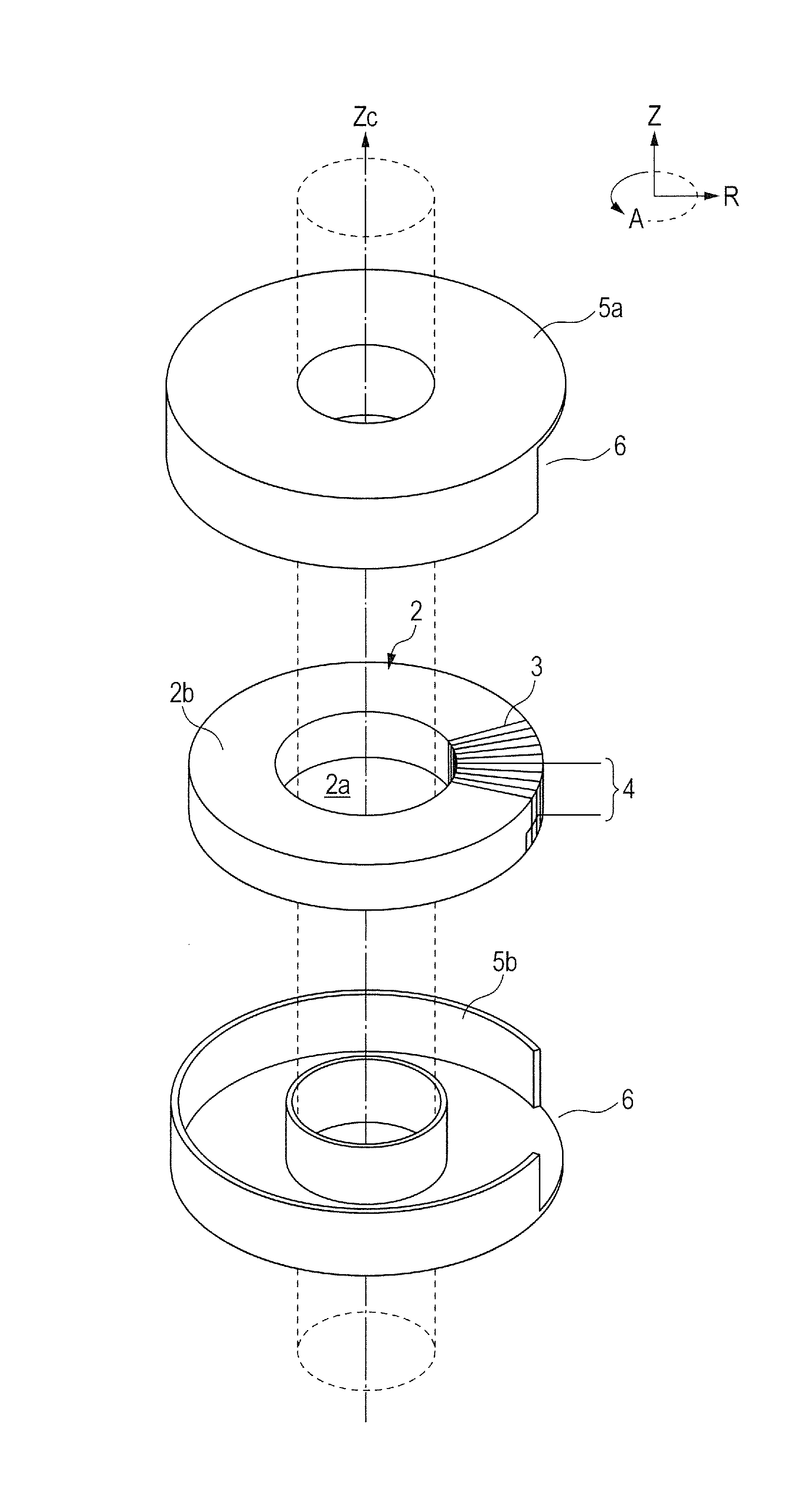
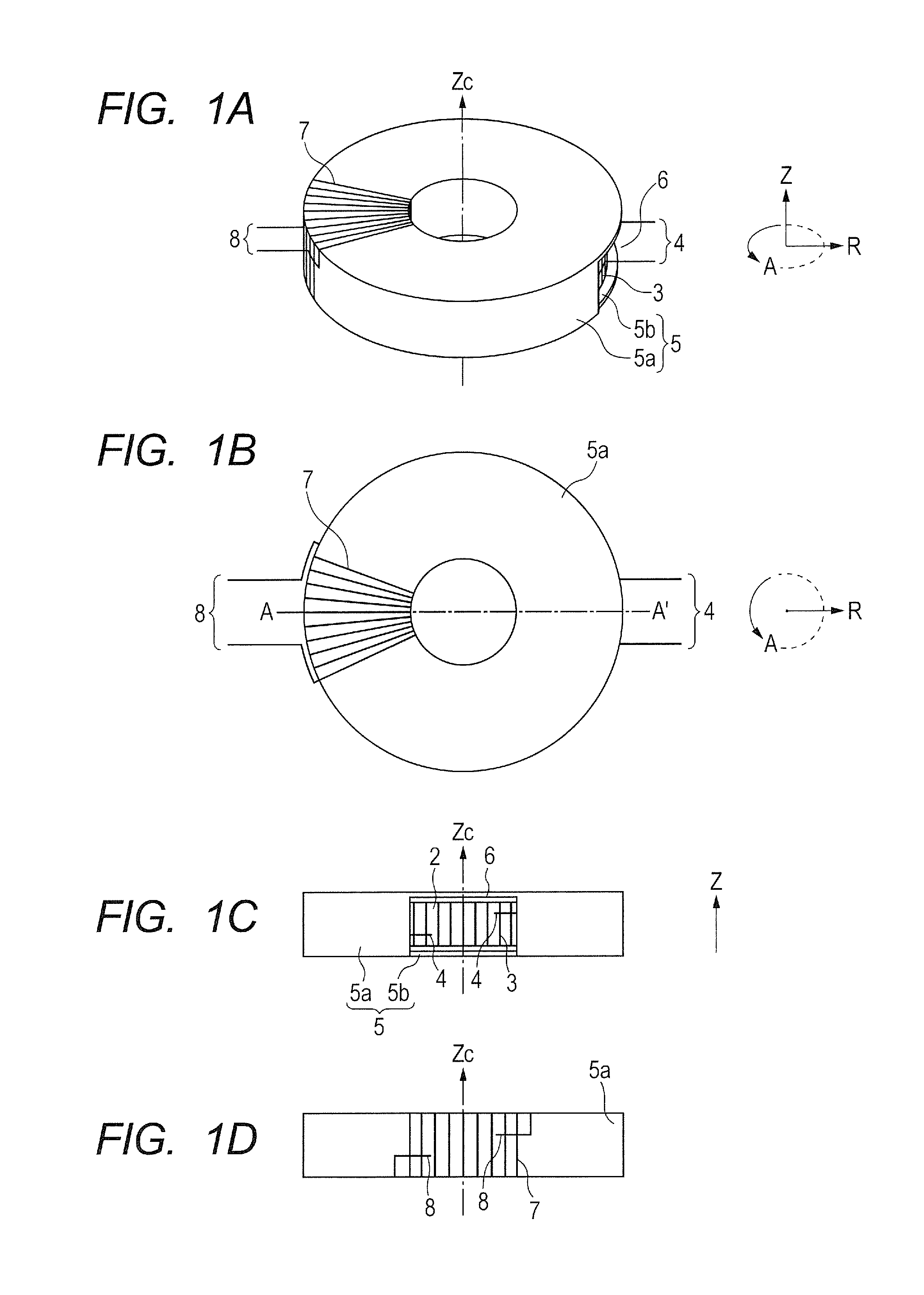
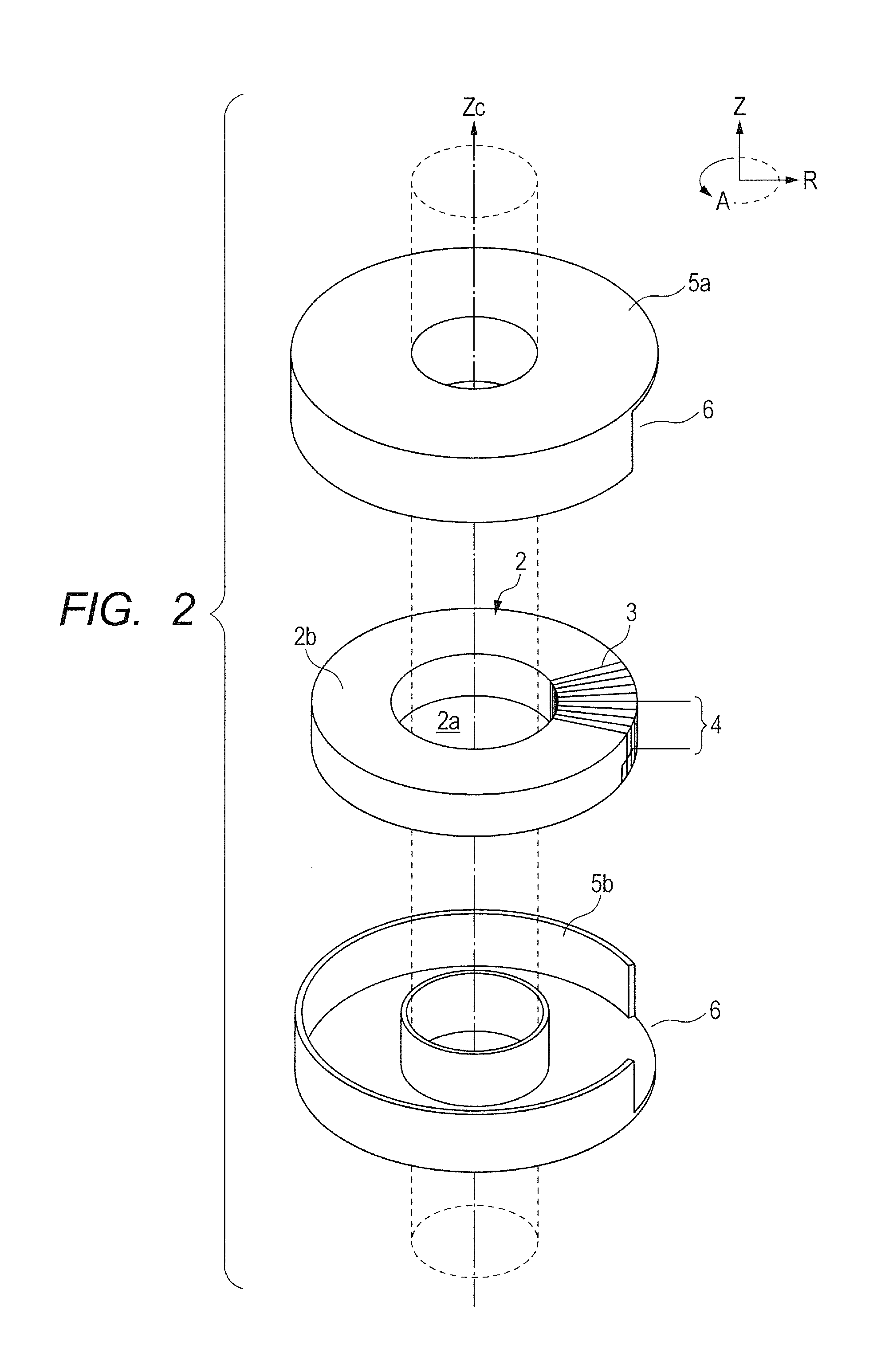
[0055]An isolation transformer was manufactured similarly to Example 1 except for using the second container 18 illustrated in FIG. 6A to FIG. 7. The second container 18 that was formed of a PEEK resin through cutting work and had an axisymmetric doughnut-shape similarly to the first container 5 was disposed concentrically with the first container 5. A cross-section of a portion of the first container 5 around which the secondary coil 7 is wound has an entire circumference larger than those of other portions thereof by about 1.2 mm, due to the existence of the secondary coil in addition to the cross-section of 10 mm×20 mm of the first container 5. The members 18a and 18b forming the second container 18 each have a thickness of 1 mm at a fitting portion and a thickness of 2 mm at portions other than the fitting portion. The members 18a and 18b were formed so that an annular hollow part formed of the second container 18 surrounded a cross-section of the first container 5 around which ...
example 4
[0057]The X-ray generating apparatus 31 of FIG. 8 was manufactured with the use of the isolation transformer of Example 3 that included a transmission type X-ray tube as the X-ray generating tube 32. A high-voltage insulating oil A (trade name; manufactured by JX Nippon Oil & Energy Corporation) was used as the insulating liquid 41. The container 42 was a brass container and had a ground potential. The container 42 had electrical connectors (not shown), by which the drive control portion 35 and the tube voltage control portion 38 disposed outside of the container 42 were respectively connected to the isolation transformer 36 and the high-voltage transformer 39 disposed inside of the container 42.
[0058]In the X-ray generating apparatus 31 of this example, the X-ray generating tube 32 had the anode having a ground potential and the cathode to which a voltage of −100 kV was applied upon the driving. Signals each based on a cathode potential were appropriately applied to the filament el...
PUM
 Abstract
Description
Claims
Application Information
 - Generate Ideas
- Intellectual Property
- Life Sciences
- Materials
- Tech Scout
- Unparalleled Data Quality
- Higher Quality Content
- 60% Fewer Hallucinations
Browse by: Latest US Patents, China's latest patents, Technical Efficacy Thesaurus, Application Domain, Technology Topic, Popular Technical Reports.
© 2025 PatSnap. All rights reserved.Legal|Privacy policy|Modern Slavery Act Transparency Statement|Sitemap|About US| Contact US: help@patsnap.com


