Circuit board assembly with high and low frequency substrates

Inactive Publication Date: 2016-07-07
DELPHI TECH INC
View PDF2 Cites 5 Cited by
  • Summary
  • Abstract
  • Description
  • Claims
  • Application Information

AI Technical Summary

Benefits of technology

[0003]In accordance with one embodiment, a circuit board assembly is provided. The circuit board assembly includes a low-frequency (LF) substrate, a monolithic microwave integrated circuit (MMIC), a plurality of electrical components, a high-frequency (HF) substrate, a plurality of wire bonds, and an antenna. The LF substrate is formed of FR-4type material. The LF substrate defines a top-side, a bottom-side, and a waveguide through the LF substrate configured to guide a radio-frequency signal from the top-side to the bottom-side. The MMIC is attached to the top-side and configured to output the radio-frequency signal. The plurality of electrical components are electrically attached to the LF substrate and configured to process a

Problems solved by technology

Standard packages such as a Quad Flat No-leads (QFN) package are not preferred for mm-wave devices as such packages do not provide suitable performance for quality RF interfaces.
High-frequency

Method used


Image

  • Circuit board assembly with high and low frequency substrates
  • Circuit board assembly with high and low frequency substrates
  • Circuit board assembly with high and low frequency substrates

Examples


Embodiment Construction

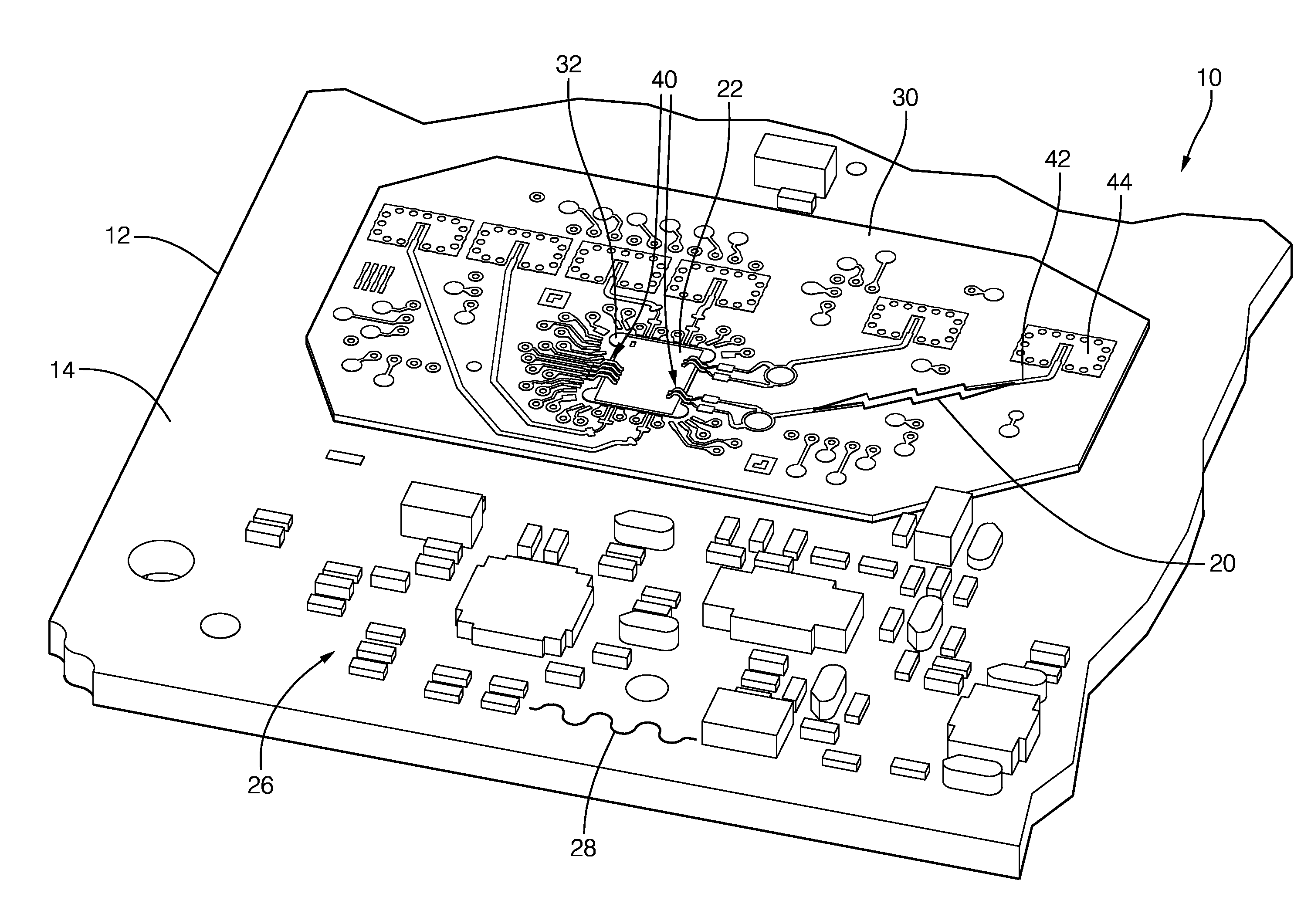
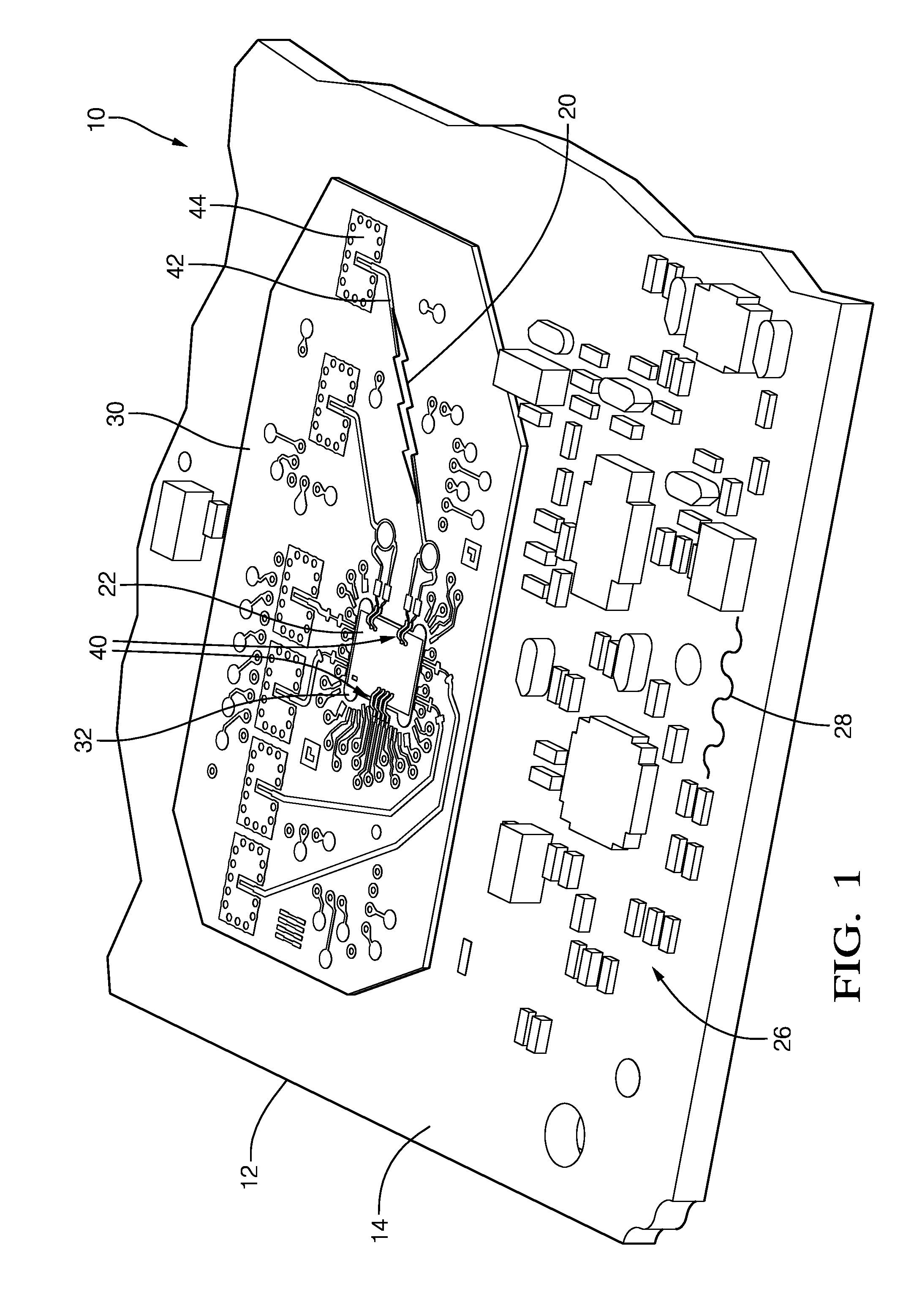
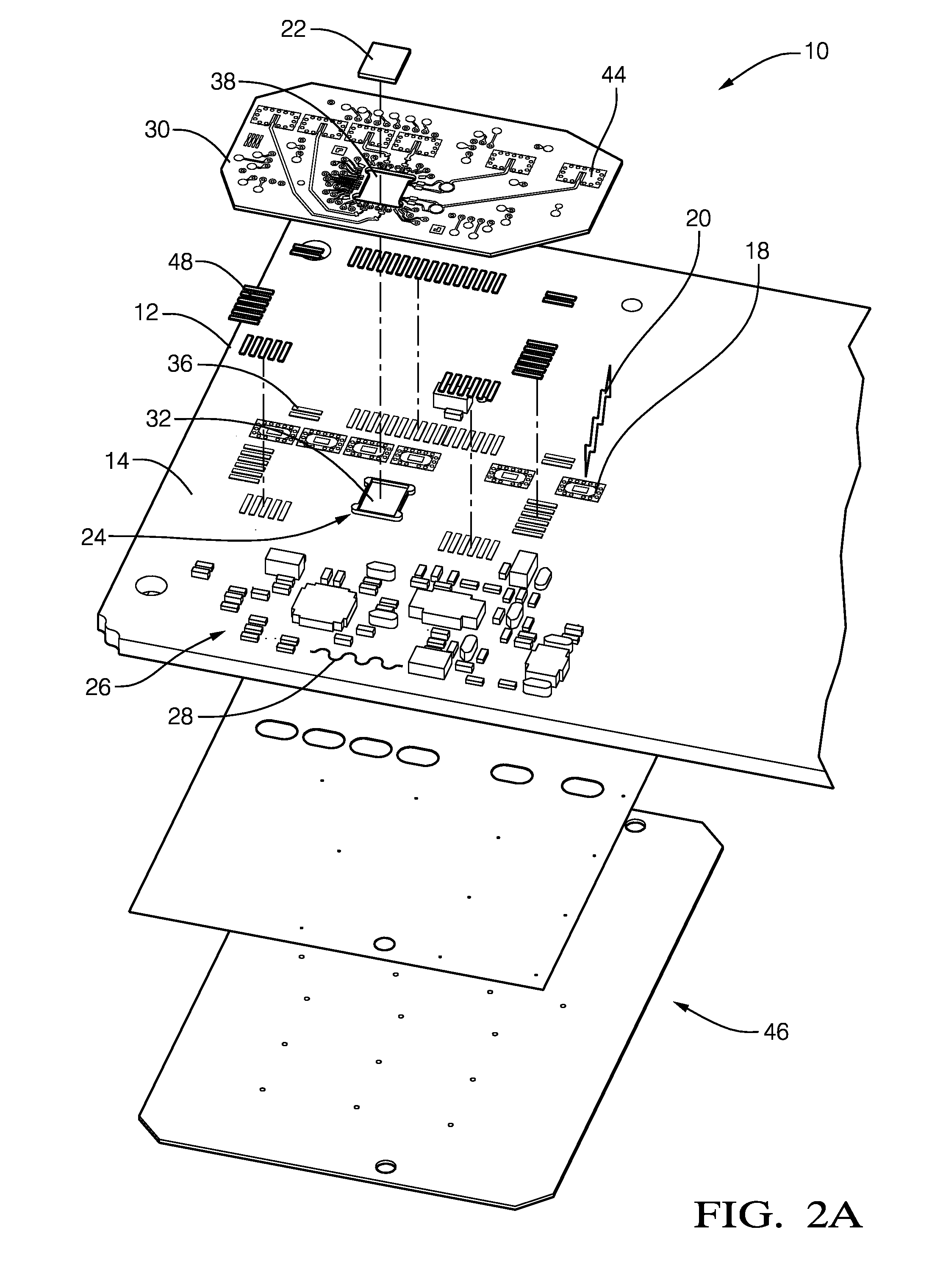
[0008]Described herein is a circuit board assembly that provides an economical assembly for electrical systems that have or process both relatively low-frequency signals with frequency spectrums less than 100 MHz, including DC power, and relatively high frequency signals, i.e. radio-frequency signals with frequency spectrums greater than 1 GHz. By way of example and not limitation, the circuit board assembly described herein would be well suited for an automotive radar system operating with a radar signal frequency of 76.5 GHz. While the description presented herein is generally directed to the transmission of a radio-frequency signal, it is recognized that the teachings are applicable to circuit board assemblies that only receive a radio-frequency signal, and both transmit and receive a radio-frequency signal as would be the case for a radar system.

[0009]FIGS. 1, 2A, 2B, and 2C cooperatively illustrate a non-limiting example of a circuit board assembly, hereafter referred to as the...


PUM


Abstract

A circuit board assembly includes a low-frequency (LF) substrate, a monolithic microwave integrated circuit (MMIC), electrical components, a high-frequency (HF) substrate, and an antenna. The LF substrate is formed of FR-4 type material. The LF substrate defines a waveguide through the LF substrate. The MMIC is attached to the top-side of the LF substrate and outputs the radio-frequency signal. The electrical components are electrically attached to the LF substrate. The HF substrate is soldered to the top side of the LF substrate. An opening through the HF substrate surrounds the MMIC. A vertical transition guides the radio-frequency signal output by the MMIC to the waveguide. A plurality of wire bonds electrically connects the MMIC to the HF substrate and couple the radio-frequency signal from the MMIC to the vertical transition. The antenna is attached to the LF substrate and configured to radiate the radio-frequency signal from the waveguide.

Description

TECHNICAL FIELD OF INVENTION[0001]This disclosure generally relates to a circuit board assembly, and more particularly relates to a cost efficient interconnection of substrates, electrical devices, and an antenna for transmitting and / or receiving a radio-frequency signal.BACKGROUND OF INVENTION[0002]It is known to include a Monolithic Microwave Integrated Circuit (MMIC) in a circuit board assembly of a cost sensitive millimeter-wavelength product such as an automotive radar system. Standard packages such as a Quad Flat No-leads (QFN) package are not preferred for mm-wave devices as such packages do not provide suitable performance for quality RF interfaces. High-frequency substrates are generally more expensive than low-frequency (e.g. FR-4) substrates, so building an entire circuit board assembly using only a high-frequency substrate undesirably increases cost. However, a packaging solution for a MMIC requires efficient transfer of radio-frequency (RF) signals via a suitable substr...

Claims


Application Information

Patent Timeline
IPC IPC(8): H01Q1/50H05K1/02
CPCH01Q1/50H05K2201/10007H05K1/02H01Q1/225H05K1/141H05K2201/10098H01L23/66H05K1/0243H05K1/184H05K3/368H05K2201/041H05K2203/049H01L2224/48472H01L2224/49175H01L2924/0002H01P5/028H01Q21/065H01L2223/6683
Inventor ZIMMERMAN, DAVID W.SEARCY, JAMES F.DELHEIMER, CHARLES I.
Owner DELPHI TECH INC
Why Eureka
Try Eureka