Powder recycling system

Inactive Publication Date: 2016-07-14
MICROJET TECH
View PDF4 Cites 28 Cited by
  • Summary
  • Abstract
  • Description
  • Claims
  • Application Information

AI Technical Summary

Benefits of technology

[0006]The present invention provides a powder recycling system for preventing the working environment from being polluted by the flying dust. After a three-dimensional object is placed within a sealed chamber of a sealed main body, an excess powder removing process can be performed to recycle the excess powder. A filter is installed in the sealed chamber and in communication with a negative pressure generator. Consequently, the excess powder removing process is performed in the sealed chamber under a negative pressure condition. Due to

Problems solved by technology

Since the processes of spreading powder, printing and taking out the finished product are manually performed according to the conventional rapid prototyping technology, the flying dust usually pollutes the working environment and contaminates the whole three-dimensional rapid prototyping apparatus.
However, during the cleaning process, the finished product is poss

Method used


Image

  • Powder recycling system
  • Powder recycling system
  • Powder recycling system

Examples


Embodiment Construction

[0013]The present invention will now be described more specifically with reference to the following embodiments. It is to be noted that the following descriptions of preferred embodiments of this invention are presented herein for purpose of illustration and description only. It is not intended to be exhaustive or to be limited to the precise form disclosed.

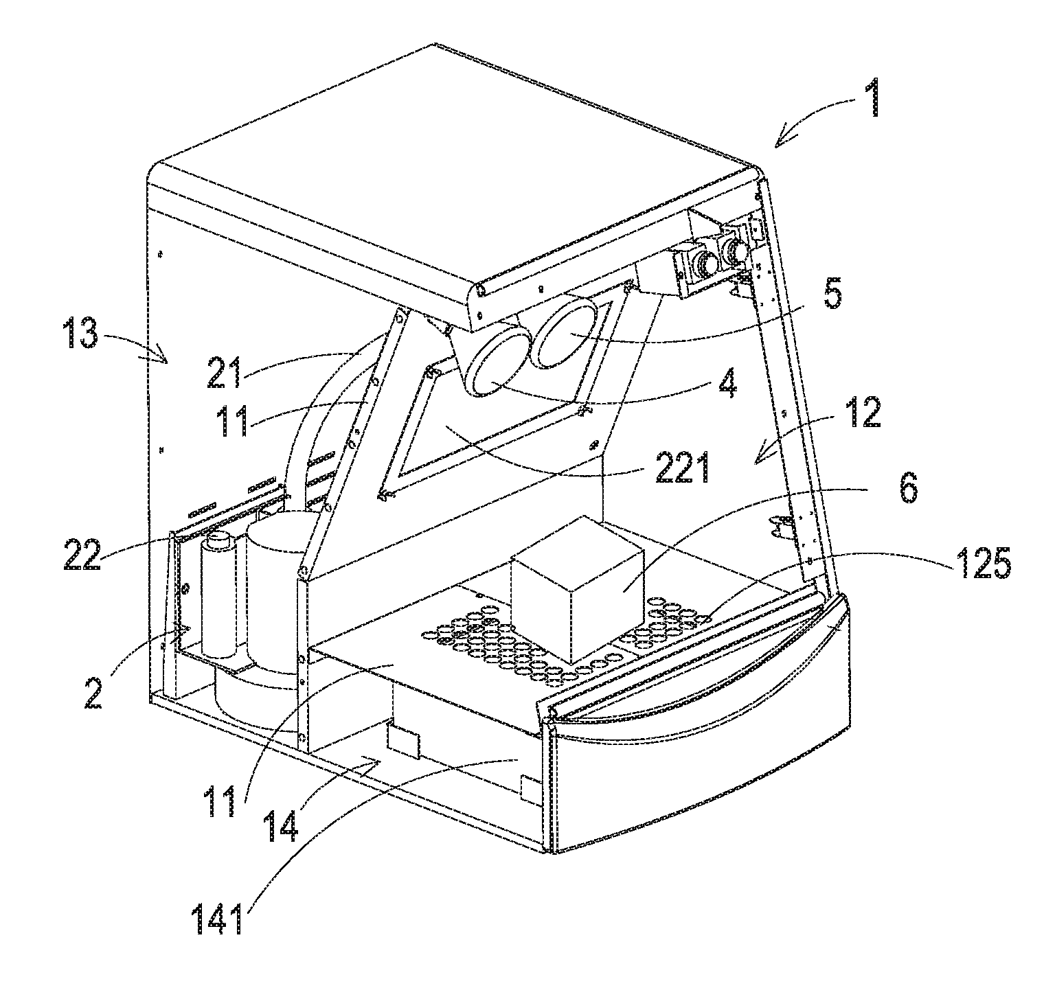
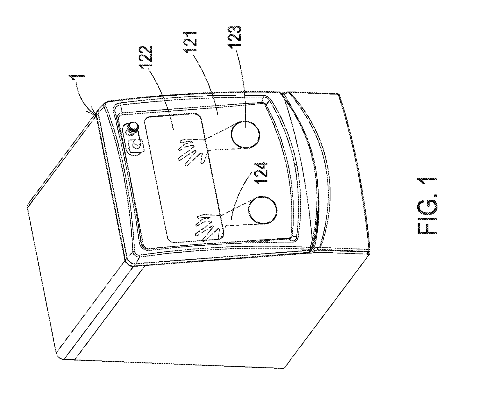
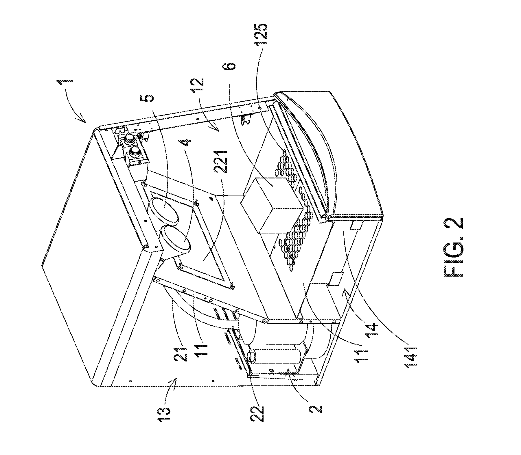
[0014]FIG. 1 is a schematic perspective view illustrating a powder recycling system according to an embodiment of the present invention. FIG. 2 is a schematic perspective view illustrating the inner structure of the powder recycling system of FIG. 1. FIG. 3 is a schematic perspective view illustrating the inner structure of the powder recycling system of FIG. 2 and taken along another viewpoint. FIG. 4 is a schematic perspective view illustrating the backside of the powder recycling system of FIG. 3.

[0015]Please refer to FIGS. 1, 2, 3 and 4. The powder recycling system comprises a sealed main body 1, a negative pressure generator...


PUM

PropertyMeasurementUnit
Pressureaaaaaaaaaa
Strengthaaaaaaaaaa
Transparencyaaaaaaaaaa

Abstract

A powder recycling system for a three-dimensional rapid prototyping apparatus is provided. The powder recycling system includes a sealed main body, a negative pressure generator, an air pressure generator, a lighting unit and a heater. When an excess powder removing process is performed to remove excess powder from a three-dimensional object, the excess powder is sieved by a screen mesh and collected by a powder collector. Consequently, the excess powder is recycled.

Description

FIELD OF THE INVENTION[0001]The present invention relates to a powder recycling system, and more particularly to a powder recycling system for a three-dimensional rapid prototyping apparatus.BACKGROUND OF THE INVENTION[0002]As known, a rapid prototyping (RP) technology is developed from the concepts of forming a pyramid by stacking layers, and the main technical feature is to achieve fast formation. A complicated design can be transformed into a three-dimensional physical model automatically and fast without any cutting tools, molds and fixtures. Thus, the development cycle of new products and research and development cost are largely reduced to ensure the time to market for new products and the first-time-right ratio. Accordingly, a complete and convenient product design tool is provided between technicians and non-technicians (e.g. managers and users), and the product competitiveness and the quick reaction capability of enterprises in the market are improved obviously.[0003]Recent...

Claims


Application Information

Patent Timeline
IPC IPC(8): B29C67/00
CPCB29C67/0096B33Y40/00B33Y30/00B29K2105/251B29C64/35B29C64/357Y02P10/25B22F12/70B22F10/10B22F10/68B22F10/73B33Y40/20B08B5/02B08B15/02B08B15/026B29C64/165B29C64/153B29C64/307B29C64/25
Inventor CHEN, CHIH-KAIHUANG, CHI-FENG
Owner MICROJET TECH
Why Eureka
Try Eureka